|
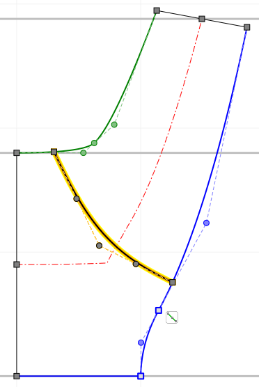
Leading and trailing edge contour can be designed as: •Bezier curve •Straight line
The edges cannot be designed, if "Leading/ Trailing edge fixed on inlet/ outlet" is selected right under "Blade edges". In case of Splitter blades each leading edge can be designed individually. |
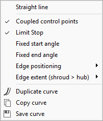
Important position and extent properties can be specified in the context menu:
|
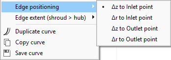
"Edge positioning" handles the axial/ radial difference from both edge endpoints to meridional inlet or outlet. The absolute value can be specified by right-click on the edge endpoint. This value remains constant during meridional shape modifications. |
|
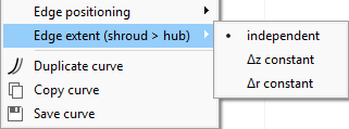
"Edge extent (shroud > hub)" controls the axial/ radial extent of the edge: •independent •Δz/ Δr constant |
The leading edge can be designed by a 4th order Bezier curve. Regarding the Bezier points, the properties are similar to the hub/ shroud curves. The only difference is the manipulation of the end points, which are located on the hub/ shroud curves always. The position of the leading edge always appears at the same relative position in a primary CFturbo design but this not mean to be a suggestion.
For centrifugal impellers with low nq < ≈30 the leading edge is often designed parallel to the z-axis. As the trailing edge is parallel to the axis too for such applications 2D-curved blades can be created. At higher specific speed nq or due to strength reasons the leading edge often is extended into the impeller suction area. Various diameters result in different leading edge blade angles - therefore 3D-curved blades are created. This leads to better performance curves, higher efficiencies and improved suction capacity for pumps.
The position of the leading edge should be chosen in a way that the energy transmission should be about equal on all meridional flow surfaces. A criterion is the approximately equal static moment S = ∫ r dx of the meridional streamlines on hub and shroud between leading and trailing edge. In the Static moment section the corresponding numerical values are displayed. Both ends of the leading edge should be perpendicular to the meridional contours of hub and shroud if possible. To obtain equal static moments on hub and shroud the trailing edge is often not parallel to axial direction - particularly at higher specific speeds (mixed-flow impellers).
Leading/ Trailing edge fixed on inlet/ outlet
The leading/ trailing edge can be fixed on meridional inlet/ outlet optionally.
Uncheck this option to detach the leading/ trailing edge from meridional inlet/ outlet and design its position and shape independently.