Troubleshooting
Surface description
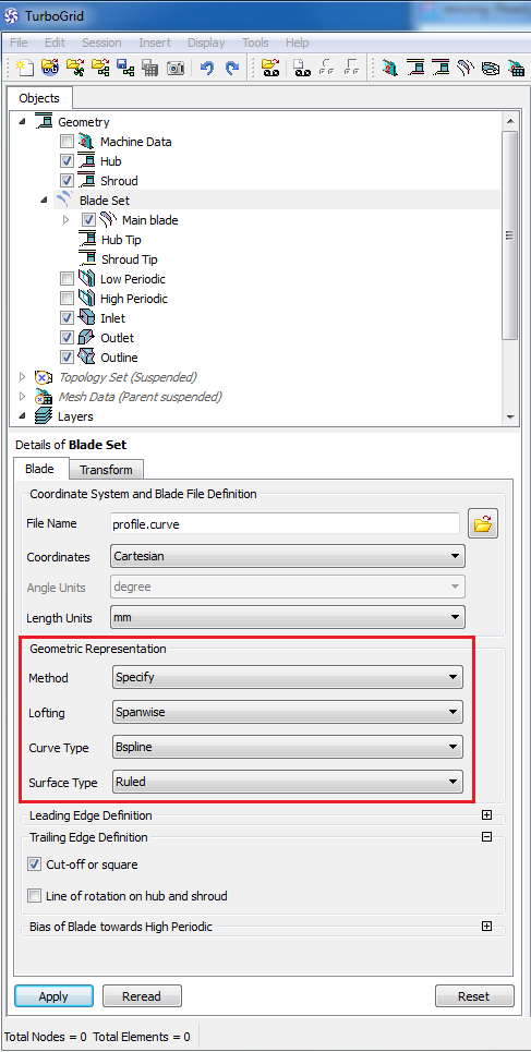
Surfaces can be described in Ansys TurboGrid by two different options: "Ruled" (linear) or "B-Spline".
More than 4 sections could result in an oscillating surface if the curves are not located exactly on the surface.
To avoid the problem you should select the Surface Type 'Ruled' under 'Blade Set' in the Ansys TurboGrid object tree.
Error extending the shroud tip line
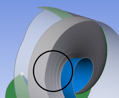
For open impellers and stators, a small region between leading/ trailing edge and meridional inlet/ outlet could result in the following error message while importing in Ansys TurboGrid:
"Error extending the shroud tip line. Try reducing the "Tip expansion factor" value."
Two options are available to increase this region:
a)moving the leading/ trailing edge in meridional contour. The edge has not to be fixed on inlet/ outlet. This option incurs a geometrical modification
b)activating a CFD extension at inlet (for radial or mixed flow turbine impellers) or outlet (for the rest of impellers) in CFD setup/ Extension. This option does not incur a geometrical modification of the component but of the neighboring one if exists.
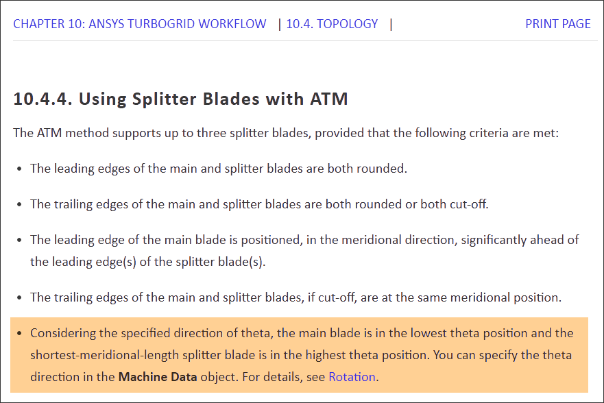
Splitter blade orientation: the selected topology is not appropriate
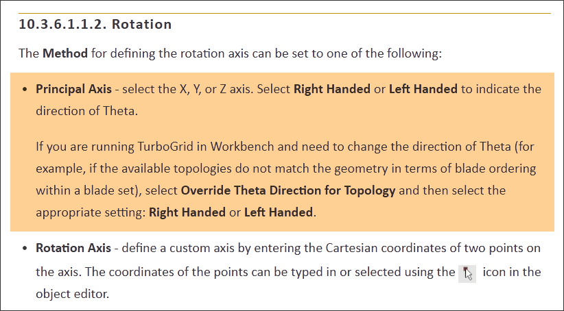
Splitter theta orientation specifies the splitter position relative to the main blade. Per default, the splitter blade is located in front of the main blade viewed in the circumferential direction, see TurboGrid user guide below. CFturbo positions the splitter blade behind the main blade.
To synchronize the positions there are 2 options available:
1.In CFturbo: Modify the splitter position from +50% to -50% (or similar values) in the Meanline design step.
2.In TurboGrid: Change the theta direction under "Rotation/ Machine Data" by switching to "Right-handed" or "Left-handed". In the GUI, TurboGrid suggests that this changes the rotation direction, but it's a new definition of the reference system only.