Computational domain
This section explains the preparation of surfaces to create the domain. This is done with the splitting, combining and renaming operations of the surfaces for all the components as follows.
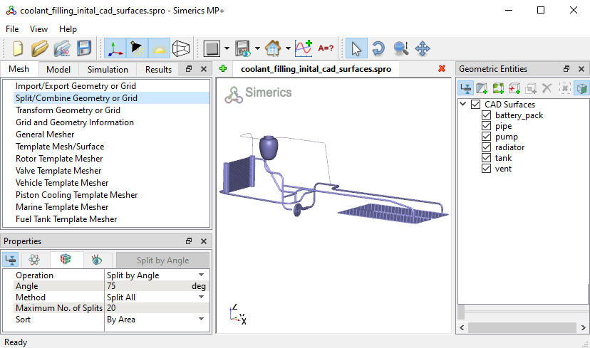
Figure 17.19 - Computational domain
Battery pack surfaces
- Select CAD Surface battery_pack and Split by Angle with Angle = 85 deg and Maximum No. of Splits = 5. Five new CAD Surfaces are created in the Geometric Entities Panel.
-
Rename the CAD Surfaces entities battery_pack_04 and battery_pack_05 as battery_pack_inlet_mgi1_pipe and battery_pack_outlet_mgi2_pipe respectively in the Geometric Entities Panel.
- Select the remaining battery pack CAD Surfaces to Combine and rename as battery_pack_wall.
|
|
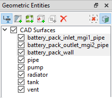
Figure 17.20 - Battery pack surfaces
|
Tank surfaces
- Select CAD Surfaces tank and Split by Angle with Angle = 85 deg and Maximum No. of Splits = 1. Ten new CAD Surfaces entities are created in the Geometric Entities Panel.
- Select CAD Surfaces tank_05, tank_07 and rename as tank_coolant_inlet, tank_air_vent_outlet respectively.
- Select CAD Surfaces tank_08, tank_09 and tank_10 and rename as tank_mgi1_pipe, tank_mgi2_vent_pipe and tank_mgi3_vent_pipe respectively.
- Select the remaining tank CAD Surfaces to Combine and rename as tank_wall.
|
|
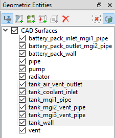
Figure 17.21 - Tank surfaces
|
Pump surfaces
- Select CAD Surfaces pump and Split by Angle with Angle = 85 deg and Maximum No. of Splits = 10. Ten new CAD Surfaces entities are created in the Geometric Entities Panel.
- Select CAD Surfaces pump_01, pump_02, pump_03, pump_04, pump_05, pump_08 and rename as volute_wall, rotor, rotor_mgi_volute, volute_mgi_rotor, rotor_inlet_mgi_pipe, volute_outlet_mgi_pipe.
- Select the remaining tank CAD Surfaces to Combine and rename as volute_rotating_wall.
|
|
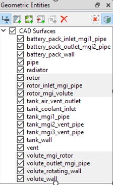
Figure 17.22 - Pump surfaces
|
Coolant pipe surfaces
- Select CAD Surfaces pipe and Split by Angle with Angle = 75 deg and Maximum No. of Splits = 9. Nine new CAD Surfaces are created in the Geometric Entities Panel.
- Rename CAD Surfaces pipe, pipe_03, pipe_04 and pipe_05 as pipe_mgi1_vent_pipe, pipe_mgi2_header1, pipe_mgi3_volute_outlet and pipe_mgi4_header2 respectively.
- Select CAD Surfaces pipe_06, pipe_07, pipe_08, pipe_09 and rename as pipe_mgi5_battery_pack_outlet, pipe_mgi6_battery_pack_inlet, pipe_mgi7_rotor_inlet and pipe_mgi8_tank.
- Select the remaining pipe CAD Surfaces to Combine and rename as pipe_wall.
|
|
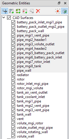
Figure 17.23 - Coolant pipe surfaces
|
Vent surfaces
- Select CAD Surfaces vent and Split by Angle with Angle = 75 deg and Maximum No. of Splits = 5. Five new CAD Surfaces are created in the Geometric Entities Panel.
- Rename CAD Surfaces vent, vent_03, vent_04 and vent_05 as vent_mgi1_tank, vent_mgi2_pipe, vent_mgi3_tank and vent_mgi4_header2 respectively.
- Select the remaining vent CAD Surfaces to Combine and rename as vent_wall.
|
|
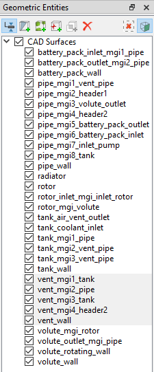
Figure 17.24 - Vent surfaces
|
Radiator surfaces
- Select CAD Surfaces radiator and Split Disconnected with Maximum No. of Splits = 2. Two new CAD Surfaces are created in the Geometric Entities Panel.
- Rename CAD Surfaces radiator, radiator_01 and radiator_02 as tubes, header2 and header1 respectively.
a) Header surfaces
- Select CAD Surfaces header1. Enter Angle = 3 deg and Method as Split by Mouse. Click Split by Angle. Click on the surfaces highlighted in red by following the numbers as shown in Figure 17.27. Two new CAD Surfaces are created in the Geometric Entities Panel.
- Select CAD Surfaces header2. Enter Angle = 3 deg and Method as Split by Mouse. Click Split by Angle. Click on the surfaces highlighted in red by following the numbers as shown in Figure 17.27. Two new CAD Surfaces are created in the Geometric Entities Panel.
- Select CAD Surfaces header1, header1_01, header1_02 and rename as header1_wall, header1_mgi1_tubes, header1_mgi2_pipe.
- Select CAD Surfaces header2, header2_01, header2_02, header2_03 and rename as header2_wall, header2_mgi1_tubes, header2_mgi2_pipe, header2_mgi3_vent_pipe.
|
|
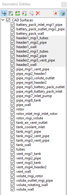
Figure 17.25 - Header surfaces
|
b) Tube surfaces
- Select CAD Surfaces tubes and Split by Angle with Angle = 75 deg and Maximum No. of Splits = 180. One eighty new CAD Surfaces are created in the Geometric Entities Panel.
- Select CAD Surfaces from tubes_001 to tubes_120. Click Combine and rename as tubes_wall.
- From the remaining CAD Surfaces from tubes_121 to tubes_180, select all CAD Surfaces attached to header1 highlighted in red on one side, as shown in Figure 17.28. Click Combine and rename as tubes_mgi1_header1.
- From the remaining CAD Surfaces from tubes_121 to tubes_180, select all CAD Surfaces attached to header2 highlighted in red on other side, as shown in Figure 17.28. Click Combine and rename as tubes_mgi2_header2.
|
|
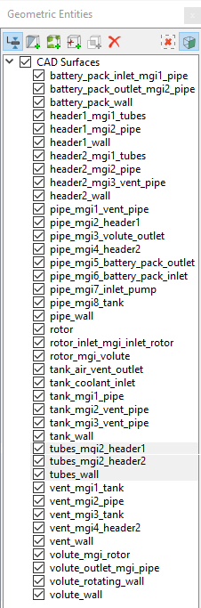
Figure 17.26 - Tube surfaces
|
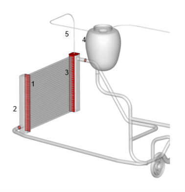
Figure 17.27 - Header - Split surfaces
|
|
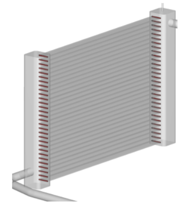
Figure 17.28 - Tube - Split surfaces
|