4.1.2 Split/Combine Geometry or Grid
This section explains the set of operations used to split CAD Surface, Boundaries, Interfaces, and Volumes. These options are accessed as follows:
Mesh Panel > Split/Combine Geometry or Grid.
The related operations are available in the Properties Panel.

Figure 4.3 - Split/Combine Geometry or Grid
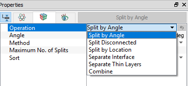
OperationThe Operation drop down list contains the following:
|
Figure 4.4 - Operation |
The details of the split/combine feature are explained as follows.
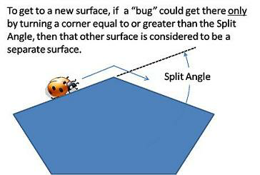
Split by Angle requires the following sub parameters to be specified:
Angle: Specifies angle for the surfaces to be split.
Method: Surfaces or boundaries are split by various methods:
- Split All: To split the whole geometry based on the specified angle and number of splits.
- Split into Two Groups: To separate the geometry into two groups based on area size and length Size.
Split by Mouse: To split the geometry using mouse, click Select
 in GUI toolbar. Click Split by Angle in the Properties Panel and select the geometry to be split in the display window.
Maximum No. of Splits: Limits the number of splits.
Sort: Splits the geometry according to the selection of By Area or By Length.
Split Disconnected
|
This is used to separate selected CAD Surfaces, Boundaries, or Volumes that do not share common points. The logic of Split Disconnected is that if surfaces, boundaries, or volumes do not share a node point, they are disconnected, even if the points are collocated. Split Disconnected requires the following sub parameters to be specified:
|
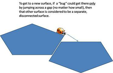
Figure 4.6 - Split disconnected |
Split by Location
This is used to separate selected CAD Surfaces, Boundaries, or Volumes based on the location.
This requires the following sub parameters to be specified:
- By Mouse: Split the geometry using mouse, specify the radius (m) and click the geometry.
- Inside A Sphere: Splits the geometry based on specified sphere radius.
- Inside A Box: Splits the geometry based on specified box dimensions.
- Separate: Splits the geometry according the Any Part Inside Faces and Complete Inside Faces selection.
Separate Interface
This is used to split an interface into two back-to-back boundaries.
Separate Thin Layer
This is used to separate thin layers of CAD Surfaces (Duplicated Surfaces) based on the minimum and maximum thickness specified (m).
Combine
This is used to combine the selected CAD Surface, Boundaries or Volumes. A common application of the Combine operation is to recombine CAD surfaces that have been split as a consequence of the surface preparation (Split by Angle and Split Disconnected) and to group entities for the convenience of handling them as a single geometric entity.
Entities should not be combined if:
- They have separate properties.
- They will use different reference frames (such as the impeller volume of a pump for a Steady State Simulation).
- The user wants to keep their respective integrated output data separate.
- The boundaries belong to separate volumes.

Figure 4.7 - Split/Combine Geometry or Grid