|
You are here: Automotive Templates and Tutorials > Automotive Tutorials > Dual Heat Exchanger Tutorial > Contours
|
Contours
The most common contours for the dual heat exchanger simulation are the temperature contours on air-side and coolant-side radiators. The results for specified inlet temperature simulation are shown below.
The steps to create contours are:
- Click Load Results in the Simulation Panel.
- Select the required result file in the ensuing Load Results dialog box, click Open.
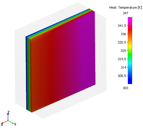
Temperature contours - Air
- Select radiator Volume in the Geometric Entities Panel.
- Select Temperature from the Variables list under Variable drop-down list in the Results Panel (see, Figure 7.332). For variables and legends, refer Post-Processing.
- Specify Min as 303 K and Max as 347 K in the Results Panel.
| Note: Changes to the display, such as legend, contour color, image sizing, transparency can be made under the View Tab of Properties Panel. |
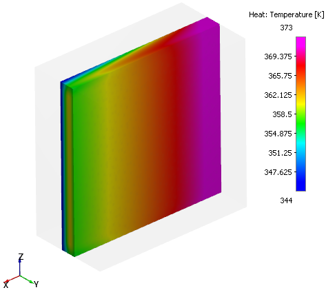
Temperature contours - Coolant
- Select radiator_linkedVolume in the Geometric Entities Panel.
- Select Temperature from the Derived Variables list under Variable drop-down list in the Results Panel (see, Figure 7.333).
- Specify Min as 344 K and Max as 373 K in the Results Panel.
| ´ | Note: Changes to the display, such as legend, contour color, image sizing, transparency can be made under the View Tab of Properties Panel. |