7.2.2 Mesher
This section explains the settings available in the Fuel Tank template to generate the dynamic mesh. The template enables the creation of mesh with appropriate quality and minimal user effort. The mesh related settings are accessed by selecting Fuel Tank Template Mesher in the Mesh Panel.
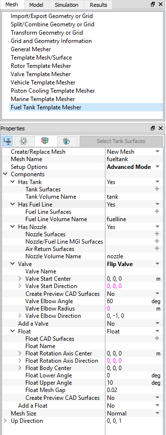
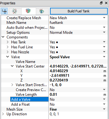
The following mesh related settings are available in the Geometry Tab of the Properties Panel as shown in Figure 7.80.
Create/Replace Mesh: Allows the user to select one of the following:
- New Mesh: To create a new mesh.
- Store Build Mesh: To store the mesh settings without generating any mesh.
- Replace: gerotor: To replace the existing mesh with new mesh settings.
Mesh Name: Allows the user to name the mesh prior to mesh creation. This option is available when New Mesh or Store Build Mesh is selected under Create/Replace Mesh.
Setup Options: Allows the user to create the mesh using one of the following modes:
- Normal Mode: This mode provides standard access to the basic parameters to create the mesh.
- Advanced Mode: This mode provides full access to all the meshing parameters to create the mesh.
Components: The option has following input variables Has Tank, Has Fuel Line, Has Nozzle, Add a Valve, and Add a Float.
- Has Tank: Select Yes to add tank and provide the Tank Surfaces and Tank Volume Name.
- Has Fuel Line: Select Yes to add fuel line and provide Fuel Line Surfaces and Fuel Line Volume Name.
- Has Nozzle: Select Yes to add nozzle and provide Nozzle Surfaces, Nozzle/Fuel Line MGI Surfaces, Air Return Surfaces and Nozzle Volume Name.
- Add a Valve: Allow you to select Flip Valve, Spool Valve and Dummy Valve. Upon selection of required valve the respective options are activated.
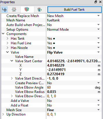
- Flip Valve: Upon selection of the Flip Valve the following parameters are activated see, Figure 7.82
- Valve Name: Provide valve name
- Valve Start Center: Provide valve center in X,Y,Z.
- Valve Start Direction: Provide the start direction in X,Y,Z.
- Create Preview CAD Surfaces: Creates preview of flip valve CAD after providing all parameters.
- Valve Elbow Angle: Provide the maximum angle of valve displacement in degree.
- Valve Elbow Radius: Provide radius of elbow.
- Valve Elbow Direction: Provide the direction of the elbow.
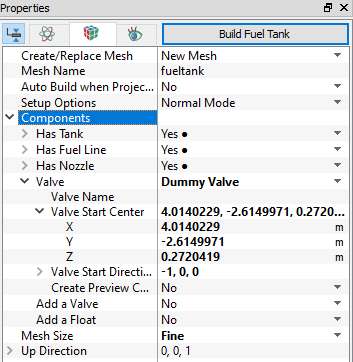
- Dummy Valve: Upon selection of the Dummy Valve the following parameters are activated see, Figure 7.83.
- Valve Name: Provide valve name
- Valve Start Center: Provide valve center in X,Y,Z.
- Valve Start Direction: Provide the start direction in X,Y,Z.
- Create Preview CAD Surfaces: Creates preview of dummy valve CAD after providing all parameters.
- Spool Valve: Upon selection of the Spool Valve the following parameters are activated see, Figure 7.84
- Valve Name: Provide valve name
- Valve Start Center: Provide valve center in X,Y,Z.
- Valve Start Direction: Provide the start direction in X,Y,Z.
- Create Preview CAD Surfaces: Creates preview of spool valve CAD after providing all parameters.
- Valve Length: Provide the maximum valve length.
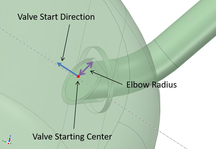
Figure 7.81 - Flip valve parameters
|
|
|
|
|
|
- Add a Float: Allows to add float. Upon selection of Float the respective options are activated.
- Float CAD Surfaces: Provide the CAD surfaces of float body.
- Float Name: Provide the name of float
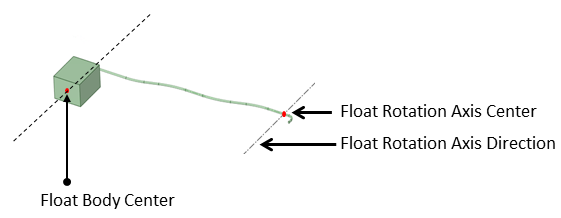
- Float Rotation Axis Center: Provide the rotational axis of the float body in X,Y,Z see, Figure 7.85.
- Float Rotation Axis Direction: Provide the rotational axis direction of the float body in X,Y,Z see, Figure 7.85.
- Float Body Center: Provide the center of the float body in X,Y,Z see, Figure 7.85.
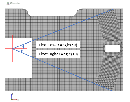
- Float Lower Angle: Provide lower angle of float displacement see, Figure 7.86.
- Float Upper Angle: Provide upper angle of float displacement. The sign of these two angle based on the rotational axis direction see, Figure 7.86.
- Float Mesh Gap: Provide mesh gap between float solid and cylinder see, Figure 7.87.
- Create Preview CAD Surfaces: Creates preview of float CAD after providing all parameters.
|
|
|
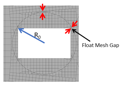
| Note: tank_float_gap” specifies the gap between float solid and cylinder, as well as the gap between cylinder and arches. It is a relative length based on R0. Notice a small gap requires a small minimum cell size to resolve. |
Mesh Size: This allows to control the resolution of the created mesh, by selecting the specified parameters as Coarse, Normal, Fine, and User Input. For more information on user input, refer General Mesher.
Up Direction: Provide the direction in terms of X, Y, and Z against gravity direction.
Once the parameters for meshing are defined, click Build Fuel Tank in the Geometry Tab of the Properties Panel. The fueltank mesh is created and added under Built Meshes, and the corresponding Volumes are generated in the Geometric Entities Panel. Also, Fuel Tank module is added to the Model Panel. Similarly with float volumes are created under Volumes.