|
You are here: Automotive Templates and Tutorials > Vehicle Template > Vehicle Underhood Thermal Tutorial > Contours
|
Contours
The most common contours are velocity magnitude, total pressure coefficient and pressure contours across the domain. The steps to create contours are:
- Click Load Results in the Simulation Panel.
- Select the required result file in the ensuing Load Results dialog box, click Open.
Create a section
A section is created with the following steps.
- Click Create a Cross-Section
 icon in the Geometric Entities Panel. A new section Section 01 is created under Derived Surfaces.
 - Select the Section 01 under Derived Surfaces and specify the Type as Plane Y in the Geometry Tab of Properties Panel.
Temperature Contour
- Select Section 01 under Derived Surfaces in the Geometric Entities Panel.
-
Select Temperature under Derived Variables list for the Variable drop-down list in the Results Panel.
-
Change the Display unit to C in Display Variable under Surface in the View Tab of Properties Panel.
-
Specify Min as 30 C and Max as 200 C in the Results Panel.
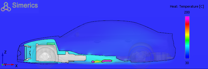
Figure 7.68 - Temperature Contour at mid plane
Fuel Tank Contour
- Select fuel_tank under Volumes in the Geometric Entities Panel.
-
Select Temperature under Variables list for the Variable drop-down list in the Results Panel.
-
Specify Min as 35 C and Max as 40 C in the Results Panel.
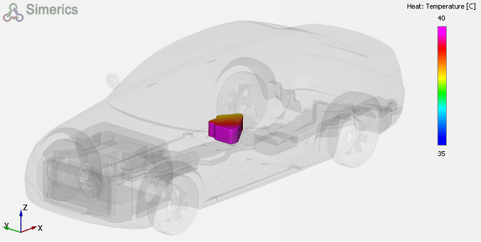
Figure 7.69 - Fuel Tank temperature Contour
Exhaust Pipe contour
- Select Boundaries exhaust_catalytic_converter, exhaust_muffler_v1, exhaust_pipe_1, exhaust_pipe_2, exhaust_tail_pipe_1, exhaust_tail_pipe_2 under Volumes in the Geometric Entities Panel.
- Select Temperature under Variables list for the Variable drop-down list in the Results Panel.
-
Specify Min as 35 C and Max as 500 C in the Results Panel.
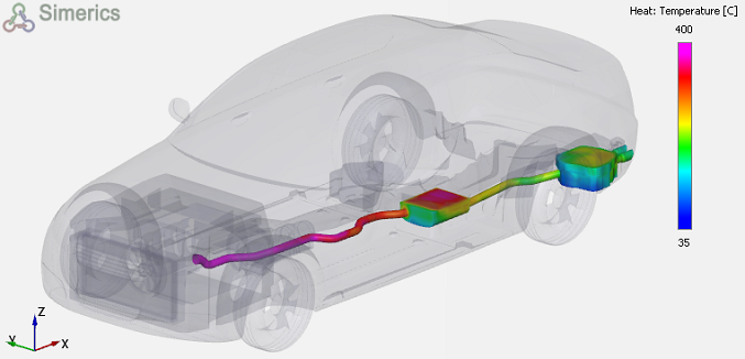
Figure 7.70 - Exhaust System Temperature Contour