Building the Mesh
This section describes the step-by-step procedure to prepare the mesh for the Data exchange model that contains inlet, outlet, gear and casing.
The mesh for the computational domain is created using the General Mesher. The settings for the mesh generation are explained in Table 10.1.
Inlets and Outlets
- Select General Mesher in the Mesh Panel.
- Enter Mesh Name as inlet_outlet.
-
Select inlet_inlet, inlet_mgi, inlet_wall, outlet_mgi, outlet_outlet and outlet_wall from the CAD Surfaces in the Geometric Entities Panel.
- Enter the Maximum Cell Size as 0.02, Minimum Cell Size as 0.0007 and Cell Size on Surfaces as 0.01 in the Properties Panel.
- Click Create Mesh. A new mesh inlet_outlet is created under Built Meshes in the Geometric Entities Panel.
- The meshed Volume inlet and outlet are generated under Volumes.
|
|
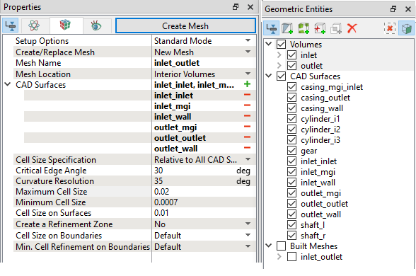
Figure 10.15 - Inlets and Outlet mesh settings
|
Casing
- Select General Mesher in the Mesh Panel.
- Enter Mesh Name as casing.
-
Select casing_inlet, casing_outlet, casing_wall, cylinder_i1, cylinder_i2, cylinder_i3, shaft_l and shaft_r from the CAD Surfaces in the Geometric Entities Panel.
- Enter the Maximum Cell Size as 0.02, Minimum Cell Size as 0.0004 and Cell Size on Surfaces as 0.01 in the Properties Panel.
- Click Create Mesh. A new mesh casing is created under Built Meshes in the Geometric Entities Panel.
- The meshed Volumescasing and casing_1 are generated under Volumes. Delete casing_1 under Volumes.
|
|
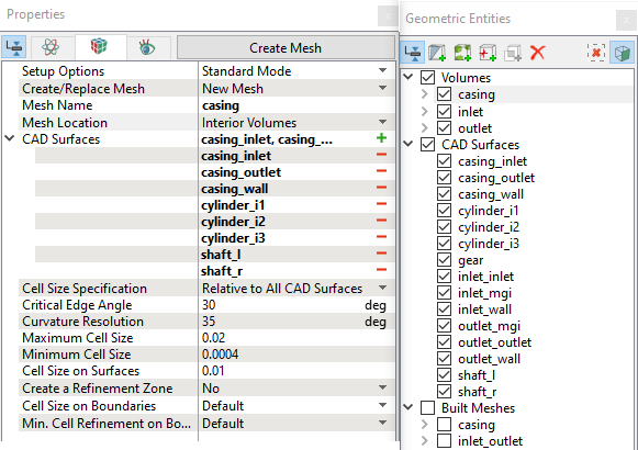
Figure 10.16 - Casing Mesh settings
|
Cylinder
- Select General Mesher in the Mesh Panel.
- Enter Mesh Name as cylinder.
-
Select cylinder_i1, cylinder_i2, cylinder_i3, gear, shaft_l and shaft_r from the CAD Surfaces in the Geometric Entities Panel.
- Enter the Maximum Cell Size as 0.02, Minimum Cell Size as 0.0004 and Cell Size on Surfaces as 0.01 in the Properties Panel.
- Click Create Mesh. A new mesh cylinder is created under Built Meshes in the Geometric Entities Panel.
- The meshed Volumes cylinder and cylinder_1 are generated under Volumes. Delete cylinder under Volumes and rename cylinder_1 as cylinder.
|
|
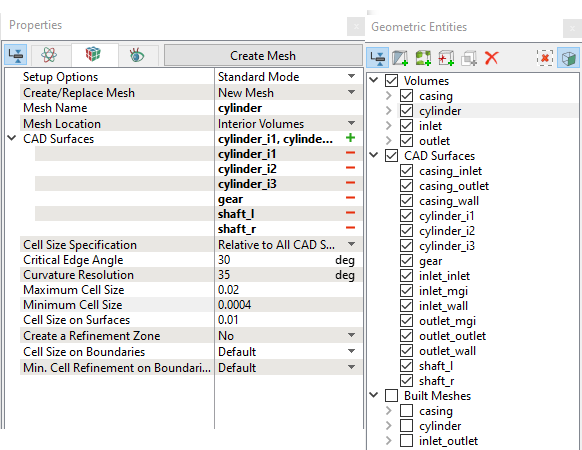
Figure 10.17 - Cylinder Mesh settings
|
Layer mesh on Gear and Shaft
- Select Template Mesh/Surface in the Mesh Panel.
- Select Layer from the Shape drop-down list in Geometry Tab of Properties Panel.
-
Select gear, shaft_l and shaft_r from the Boundaries list under cylinder Volume in the Geometric Entities Panel.
-
Click Add Surfaces icon for Surfaces in the Properties Panel. icon for Surfaces in the Properties Panel.
-
Enter the Thickness as 0.0002, Cell Size on Wall as 5e-5 and Num. of Layers as 3.
- The meshed Volume layer is generated under Volumes.
|
|
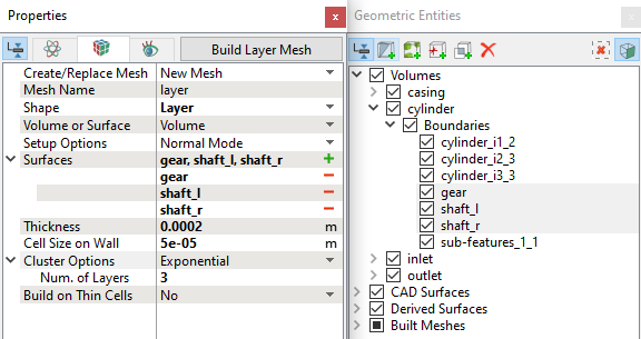
Figure 10.18 - Layer Mesh settings
|
The mesh created for the fluid domain is shown below:
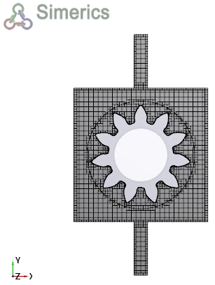
Figure 10.19 - Cross sectional view (Z=0.014)
Create interfaces
In this section, the Mismatched Grid Interfaces (MGIs) are generated between boundaries.
The steps to create the MGIs are shown below:
- In Geometric Entities Panel > Volumes > Boundaries, select Boundaries as shown in Table 10.1.
- Click Connect Selected Boundaries via MGI
 icon to create the MGI entities.
A group display of entities can be viewed using the Group Entities by Volumes/Types  icon at Geometric Entities Panel toolbar.
| Inlet and casing |
inlet_mgi and casing_inlet |
MGI01 |
| Casing and cylinder |
cylinder_i1 and cylinder_i1_1 |
MGI02 |
| Casing and cylinder |
cylinder_i2 and cylinder_i2_2 |
MGI03 |
| Casing and cylinder |
cylinder_i3 and cylinder_i3_2 |
MGI04 |
| outlet and casing |
outlet_mgi and casing_outlet |
MGI05 |
Table 10.1 - Creating interfaces
| ´ |
Note: If MGIs are created by connecting the wrong Boundaries, delete the created MGIs by clicking on Delete Selected Geometric Entity icon and then recreate the MGIs. icon and then recreate the MGIs.
|