10.1 Data Exchange Module and Tutorial
Data exchange module in Simerics-MP+ is used to simulate heat transfer between fluid and solid in a coupled manner. Traditionally, Conjugate Heat Transfer (CHT) simulation is followed in which fluid and solid are modelled together. The heat flux and the wall temperature across the conjugate interface are predicted as part of the solution and no separate treatment is required. However, the CHT approach for certain practical applications (For example, Emotor cooling and Piston cooling) is computationally expensive due to heat transfer time scale difference between fluid and solid. Usually, temperature changes in solids occur over a much slower time-scale due to their higher thermal inertia compared to faster convective and diffusive heat transfer in fluid.
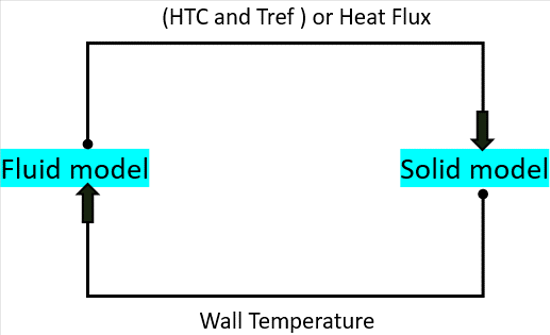
The barrier of time scale difference is addressed by using data exchange module in Simerics-MP+. The module synonymously is also called as mixed-time scale module. In the approach, fluid and solid domains are modelled separately. The heat flux and temperature boundary conditions are exchanged between the domains during the progress of the simulation. Both steady and transient heat simulations can be performed using the module. Data exchange module is not limited to conjugate heat transfer but can be used for any heat transfer simulation. A pictorial representation of the module is shown in Figure 10.1.
|
To activate the Data Exchange module:
|
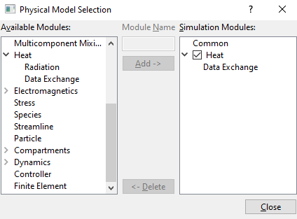
| ´ | Note: Data Exchange module must be added in both solid and fluid models separately. |
The module is explained as follows:
- Controller Parameters: Parameters used in Data Exchange module for fluid and solid models.
- Output Variables: Outputs from the Data Exchange module.
The list of parameters available under Data Exchange module in the Properties Panel is different for fluid model and solid model.
Conditions for the Fluid ModelThe Data exchange conditions, and associated parameters for fluid model boundaries are specified as follows: |
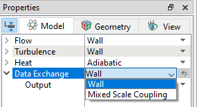
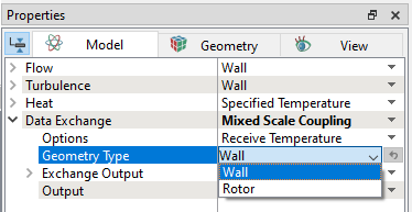
The two options available under Data Exchange drop-down list, as shown in Figure 10.3 are:
- Wall: This is the default boundary condition for the Data Exchange in the Properties Panel. This implies no temperature field and heat flux are exchanged at this selected boundary.
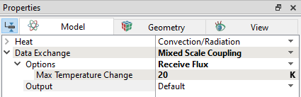
- Mixed Scale Coupling: This boundary is selected to exchange the boundary conditions between fluid and solid models. It has the following more sub-options as shown in Figure 10.4.
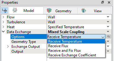
Options
The list of boundary conditions available under Options are shown in the Figure 10.4. This allows to define the thermal boundary condition for the fluid model received from the solid model.
|
The Rotor option has additional parameters as shown in Figure 10.6.
|
 } coordinate lying on the Rotational Axis Vector.
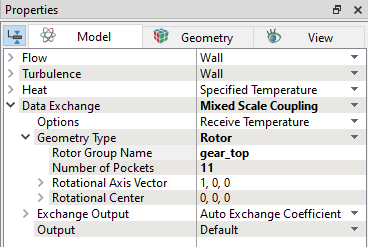
Exchange Output
The output from the fluid model is exchanged with the solid model by selecting the options as given in Figure 10.7. The default exchange output with the solid model is Auto Exchange Coefficient.
|
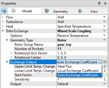
Upper Limit Temp. Change
This is the maximum allowable temperature change. If oscillations are observed in flux balance, this parameter can be varied. For example, from default value of 20K to 10K.
Lower Limit Temp. Change
This is the maximum allowable temperature change. If flux convergence is slow, this parameter can be increased. For example, from default value of 1K to 2K.
Start Factor
Initial jump in the flux imbalance can be controlled using this parameter. Initial jump in flux is directly proportional to Start Factor.
Sensitivity
If flux is converging slow in the simulation, this parameter can be increased for a faster convergence. For example, from default value of 1K to 3K. Conversely, if the flux balance shows oscillations, the value can be lowered. For example, from 1K to 0.1K.
The two options available under Data Exchange drop-down list, as shown in Figure 10.8 are:
- Wall: This is the default boundary condition for the Data Exchange in the Properties Panel. This implies no temperature field and heat flux are exchanged at this selected boundary.
- Mixed Scale Coupling: This boundary is selected to exchange the boundary conditions between fluid and solid models. It has the following more sub-options as shown in Figure 10.9.
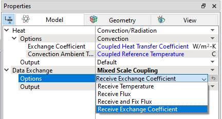
Solid Options
The list of boundary conditions available under Options are shown in the Figure 10.9. This allows to define the thermal boundary condition received from the fluid model.
|
|
Output Variables
The outputs available from the Data Exchange module are:
-
Solid Flux: This plots the exchange of heat flux from solid to fluid at the solid/fluid mapped boundaries.
- Fluid Flux: This plots the exchange of heat flux from fluid to solid at the solid/fluid mapped boundaries.
- Flux Imbalance: This plots the difference between solid and fluid flux every iteration/timestep.