|
You are here: Additional Templates and Tutorials > Data Exchange Module and Tutorial > Data Exchange Module Tutorial > Defining Physics and Conditions
|
Defining Physics and Conditions
The physics and conditions are specified as follows:
Adding Modules
|
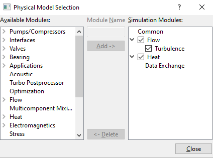
Figure 10.20 - Adding modules |
Common
|
Data Exchange
|
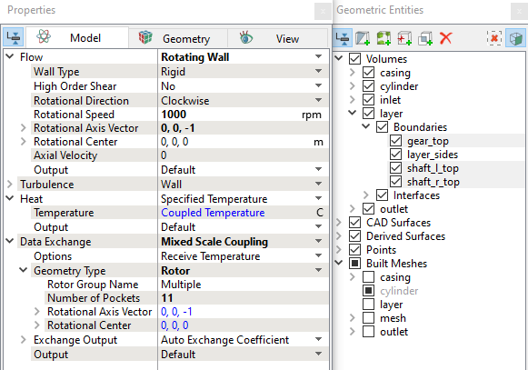
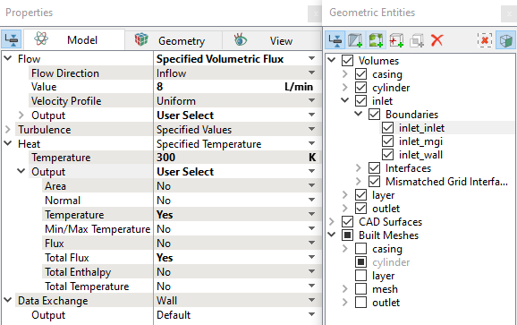
Boundary conditions
The boundary conditions are specified as follows:
Outlet
|
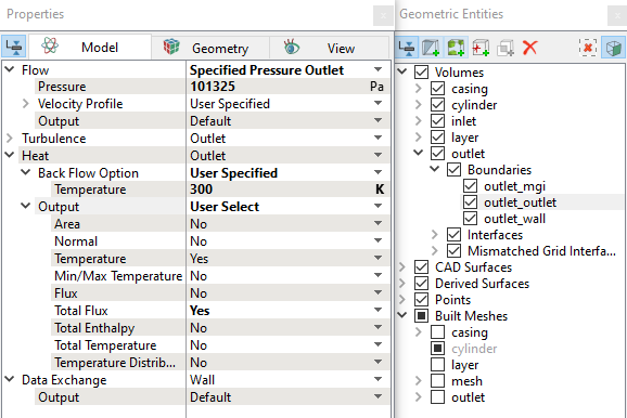
Figure 10.24 - Outlet conditions |
Fluid properties
|
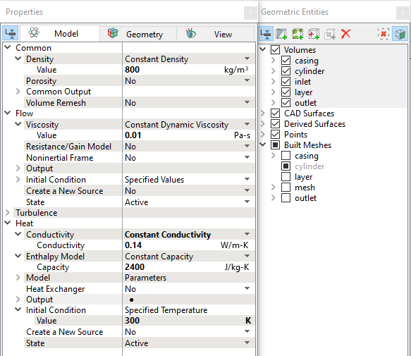
Figure 10.25 - Fluid properties |
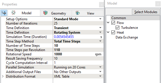
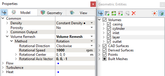
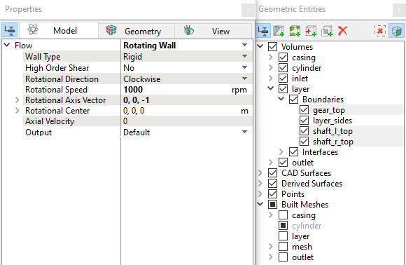
Rotating Conditions
|
|
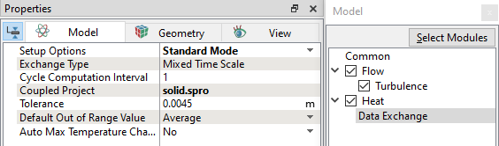
Fluid Coupling Condition
|