13.2 Basics of Expression Editor
The following concepts explain how to use the Expression Editor:
13.2.1 Rules and Options
This section lists the rules for the Expression Editor.
Rule 1: Expressions statements are separated by a space/tab/carriage return.
Rule 2: An expression statement does not need to be fit in a single line.
Rule 3: Comments can be added using the # mark. Any text in the line after “#” will not be used in the expression.
Example 1:
# Pump center coordinates
Pcx = 0
Pcy = 0
Pcz =0.01
| ´ | Note: For user defined variable for 3D Display/Plot, special formatted comments are used to redefine display/ plot name with unit. |
Rule 4: A user defined variable has to be defined before it can be used. (Otherwise an error message will be returned when the program is running and attempts to use it.)
Example 2:
# the following are valid statements
a=1 b=2 c=3
d=4
# the following are invalid statements
b=5
b=7 # variable "b" redefined
Rule 5: A variable (e.g. “amp” below) cannot be redefined within the same section and will give an error message when trying to save it (i.e. click OK ).
Example 3:
#An expression for setting a sinusoidal pressure as a function of time
f = 50
one_atm = 101325
po = 4*one_atm
amp = 2*one_atm
high_p = po+amp*(0.5*sin(2*pi*f*time))
Rule 6: The expressions are executed according to the order of each statement.
Rule 7: Expressions can operate on both variable types-Scalars and Vectors.
13.2.2 Global and Local Expressions
The Expression Editor has two sections for entering expressions: Global and Local. A Global Expression is available everywhere, while Local expressions can only be applied to a single selected object/variable.
Rule 8: Global Expressions are executed before Local Expressions.
Rule 9: Variables defined in the Global Expressions can be used inLocal Expressions.
Rule 10: If a variable defined in a Local Expressions has the same name as a variable in the Global Expressions, the Local one will be used.
The following Figure 13.3 shows an example of a Global Expressions for sinusoidal pressure (high_p) that could be used anywhere throughout the active modules along with a Local Expression exclusively for the Additional Force term in the Dynamics Module.

13.2.3 Variable Types
The Expression Editor can operate on both Vectors and Scalars.
Scalars
A Scalar is a single real number. It can be defined by equating it to an existing scalar or an expression which creates a scalar.
Example 4:
Scalar1 = 3
Scalar2 = heat.T # where heat.T is a predefined scalar quantify from the Heat Module (the temperature )
Vectors
A Vector is three (3) ordered numbers. It can be defined using components inside a bracket [x,y,z]. It can also be defined by equating it to an existing vector or an expression of vectors.
Definition:
[x,y,z]: a vector constant where each of x,y,z can be a number or an expression of numbers.
p = q: defines "p" as a vector if "q" is a vector constant, or a vector variable, or an expression of vectors.
The x, y, & z scalar components of a vector can be accessed by appending “.x”, “.y” & “.z” respectively to the vector.
p.x p.y p.z : way to access 3 scalar components of vector p.
Example 5:
Vector = [u, v, w] # Defines a vector with components u,v,w
Vector = flow.V # where flow.V is a predefined vector from the Flow module (the velocity vector)
Vector2 = [10, 20*u, 10+flow.V.z] + vel_old - 3*grid_vel
w = flow.V.z # Retrieves the z-component of flow.V (where flow.V is a predefined vector from the Flow module )
13.2.4 Units
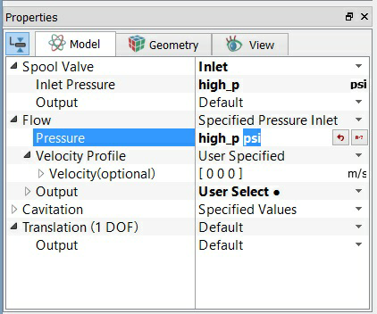
Example 6: An example is shown in Figure 13.4. When the user specifies the pressure boundary condition using a variable high_p defined in Expression Editor, the unit for inlet pressure will be "Pa" by default. The user can change the unit manually to psi. List of units available (e.g. Pa, psi, atm …) can be found in the Systems of Units menu.
|