|
You are here: Fluid Machinery Templates and Tutorials > Bent Axis Piston Pump > Mesher > Bent Axis Piston Meshing
|
Bent Axis Piston Meshing
This section explains the settings for the bent axis piston mesh generated using the Rotor Template Mesher. This involves selection of the surfaces, directional characteristics of the mesh and other advanced mesh settings.
The parameters related to Bent Axis Piston meshing can be accessed by setting the Setup Options to Advanced Mode, as shown in Figure 6.457

Figure 6.457 - Bent axis piston template mesher
Piston Wall
This is used to assign the piston surface as follows.
- Select the piston wall surface under CAD Surfaces in the Geometric Entities Panel.
- Click Add Surfaces
 icon to the right of Piston Wall, or click Select Piston Wall in the Properties Panel.
|
Note: The Select Piston Wall operation is the first in the sequence of identifying the parts of the piston pump assembly. |
Cylinder Wall
This is used to assign the wall surface of the piston cylinder as follows.
- Select the cylinder wall surface under CAD Surfaces in the Geometric Entities Panel.
- Click Add Surfaces icon to the right of Cylinder Wall, or click Select Cylinder Wall in the Properties Panel.
|
Note: The Select Cylinder Wall operation automatically follows the Select Piston Wall operation. |
Cylinder Cap
Cylinder cap rotates with the cylinder block, but unlike the cylinder wall or piston wall, does not include any scaling (compression) or translation.This is assigned as follows.
- Select the cylinder cap surface under CAD Surfaces in the Geometric Entities Panel.
- Click Add Surfaces icon to the right of Cylinder Cap, or click Select Cylinder Cap in the Properties Panel.
|
Note: The Select Cylinder Cap operation automatically follows the Select Cylinder Wall operation. |
Cylinder MGI
Cylinder MGI is the surface adjacent to Cylinder Cap which dynamically interacts with the valve plate. This is assigned as follows.
- Select the cylinder MGI surface under CAD Surfaces in the Geometric Entities Panel
- Click Add Surfaces icon to the right of Cylinder MGI, or click Select Cylinder MGI in the Properties Panel.
| Note: The Select Cylinder MGI operation automatically follows the Select Cylinder Cap operation. | |
| Note: The boundary conditions are automatically set by the template for the assigned surfaces. |
Number of Pistons
Specify the number of pistons in the pump that get created during meshing.
|
Note: The number of pistons specified during the Rotor Template Mesher operation does affect the geometry as the pistons are cloned from the a single piston assembly. This is also used in conjunction with the Time Steps Per Piston Rotation to determine the number of degrees the pistons are rotated every time-step. |
Flange Center
This is the center of the flange, located on the intersection of the flange axis of rotation and the plane containing the centers of the ball joint sockets. It is used as a Pump Configuration parameter to determine the position and motion of the pistons as the pump rotates during simulation. Specify the center in  co-ordinates .
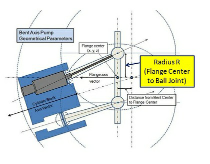
Flange Center to Ball Joint Radius
This is the distance between the Flange Center and the centers of the ball joint sockets. It is used as a Pump Configuration parameter to determine the position and motion of the pistons as the pump rotates during simulation refer, Figure 6.458. Specify the value of distance as real number in m.
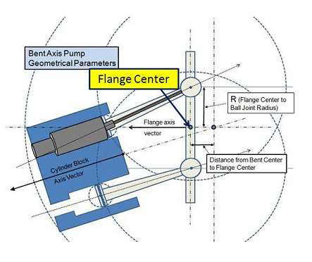
Figure 6.459 - Flange center |
Flange Axis Vector
This is the vector aligned with the axis of rotation of the flange and drive shaft in the laboratory reference frame. It is used as a Pump Configuration parameter to determine the position and motion of the pistons as the pump rotates during simulation. Specify the axis of direction in  co-ordinates.
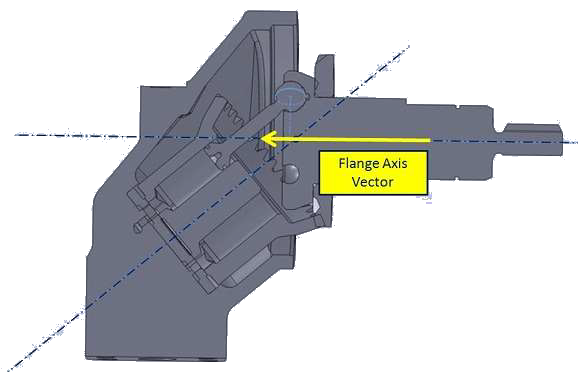
Figure 6.460 - Flange axis vector schematic: Non-articulating |
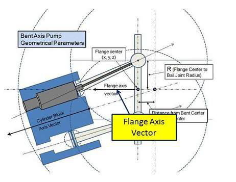
Figure 6.461 - Flange axis vector schematic: Articulating |
For single pumps and multiple pumps not connected by a common port, the above Flange Axis Vector is specified in terms of the actual alignment, which the flange and drive shaft would have in the Laboratory Reference Frame during operation. In such cases, the original CAD reference frame will be subsequently rotated during simulation such that the cylinder remains in the “neutral” position (i.e. aligned with the original Flange Axis Vector) while the Flange Plate and Drive Shaft are rotated instead. This is done for numerical optimization.

Figure 6.462 - Position of flange axis vector
|
Note: For multiple pumps connected by a common port, the Flange Axis Vector is not specified in terms of the alignment the flange plate and drive shaft during operation but must instead be specified with an additional rotation to compensate for the subsequent coordinate rotation. |
The other parameters Critical Edge Angle, Curvature Resolution, Maximum Cell Size, Minimum Cell Size and Cell Size on Surfaces are defined in General Mesher section of Panels.