|
You are here: Fluid Machinery Templates and Tutorials > Centrifugal Pump > Centrifugal Pump Tutorials > Step 1 – Creating the Steady and Transient Project Files
|
Step 1 – Creating the Steady and Transient Project Files
Setting up the model
This section describes step-by-step procedure for setting up the model for the  simulation. The CFD model setup for base transient and steady files are already prepared. User need to setup boundary conditions pertaining to
  simulation only.
| ´ | Note: This is an advanced tutorial, user must be aware of the basic model setup for the steady and transient simulation of the centrifugal pump. If not, refer Centrifugal Pump for more details. |
Importing the model for steady state project setup
The first step is to import the geometry or surfaces.
- Select File > Open. The file centrifugal_model_steady.spro from the tutorial directory in the Open Project dialog box, click Open.
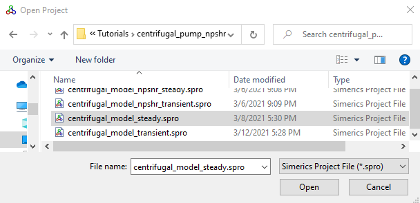
Figure 6.40 - Importing the geometry
| Note: To import .STL file refer to Import/Export Geometry or Grid. |
Boundary Conditions
-
Ensure model is setup with Steady state approach and without cavitation model.
- Ensure Inlet boundary is named as inlet_inlet and Outlet boundary as volute_outlet from the Boundaries list under Volumes in the Geometric Entities Panel, see .
- Click Edit Expression
 icon on the View Toolbar to open the Expression Editor dialog box .
 - The steady state expressions are written under the Description dropdown, the user need to copy and paste the expressions written under Description drop-down list for Global Expressions, see .
-
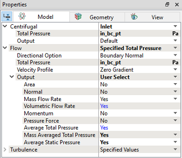
Select inlet_inlet from the Boundaries list in the Geometric Entities Panel.
- Select Specified Total Pressure from the Flow drop-down list in the Model Tab of Properties Panel, as shown in Figure 6.41
- Enter in_bc_pt Pa for Total Pressure under Flow.
- Select User Select for Output under Flow list.
- Select Yes for Mass Averaged Total Pressure and Average Static Pressure drop-down list under Flow > Output list.
-
Select volute_outlet from the Boundaries list in the Geometric Entities Panel.
- Select Specified Volumetric Flux from the Flow drop-down list in the Model Tab of Properties Panel.
- Enter Value as out_bc_qv m3/s under Flow.
- Select User Select for Output under Flow list.
- Select Yes for Mass Averaged Total Pressure and Average Static Pressure drop-down list under Flow > Output list.
-
Save the file as centrifugal_model_npshr_steady.spro (ensure it ends with _steady.spro).
in_bc_pt = 0.0 # in relevant units
out_bc_qv = 0.0 # in relevant units
in_pt=flow.pt@inlet_inlet
plot.in_pt=in_pt
in_ps = flow.p@inlet_inlet
plot.in_ps=in_ps
in_qv=flow.qv@inlet_inlet
plot.in_qv=in_qv
in_q=flow.q@inlet_inlet
plot.in_q=in_q
out_pt=flow.pt@volute_outlet
plot.out_pt=out_pt
out_ps=flow.p@volute_outlet
plot.out_ps=out_ps
out_qv=flow.qv@volute_outlet
plot.out_qv=out_qv
out_q=flow.q@volute_outlet
plot.out_q=out_q
head=flow.pt@volute_outlet - flow.pt@inlet_inlet
plot.head=head
dynamic_head=flow.pt@volute_outlet - flow.p@volute_outlet
plot.dynamic_head=dynamic_head
Inlet
|
Outlet
|
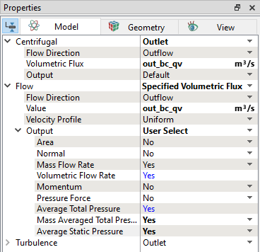
Figure 6.42 - Outlet conditions |
Importing the model for transient state project setup
The first step is to import the geometry or surfaces.
- Select File > Open. The file centrifugal_model_transient.spro from the tutorial directory in the Open Project dialog box, click Open.
![]()
Figure 6.43 - Importing the geometry
| Note: To import .STL file refer to Import/Export Geometry or Grid. |
Boundary Conditions
-
Ensure model is setup with Transient state approach and with cavitation model.
- Ensure Inlet boundary is named as inlet_inlet and Outlet boundary as volute_outlet from the Boundaries list under Volumes in the Geometric Entities Panel, see .
- Click Edit Expression icon on the View Toolbar to open the Expression Editor dialog box .
- The transient simulation expressions are written under the Description dropdown, the user need to copy and paste the text under Description drop-down list for Global Expressions, see .
-
Select inlet_inlet from the Boundaries list in the Geometric Entities Panel.
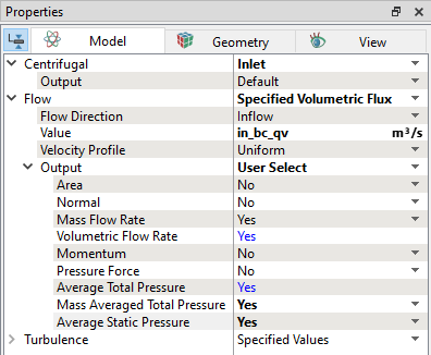
- Select Specified Volumetric Flux from the Flow drop-down list in the Model Tab of Properties Panel, as shown in Figure 6.44.
- Enter Pressure as in_bc_qv m3/s under Flow.
- Select User Select for Output under Flow list.
- Select Yes for Average Static Pressure and Mass Averaged Total Pressure drop-down list under Flow > Output list.
-
Select volute_outlet from the Boundaries list in the Geometric Entities Panel.
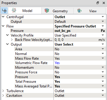
- Select Specified Pressure Outlet from the Flow drop-down list in the Model Tab of Properties Panel, as shown in Figure 6.45.
- Enter Pressure as out_bc_ps Pa under Flow.
- Select User Select for Output under Flow list.
- Select Yes for Pressure, Total Pressure and Mass Averaged Total Pressure drop-down list under Flow > Output list.
-
Save the file as centrifugal_model_npshr_transient.spro (ensure it ends with _transient.spro).
in_bc_qv = 0.0 # in relevant units
out_bc_ps = 0.0 # in relevant units
in_pt=flow.pt@inlet_inlet
plot.in_pt=in_pt
in_ps = flow.p@inlet_inlet
plot.in_ps=in_ps
in_qv=flow.qv@inlet_inlet
plot.in_qv=in_qv
in_q=flow.q@inlet_inlet
plot.in_q=in_q
out_pt=flow.pt@volute_outlet
plot.out_pt=out_pt
out_ps=flow.p@volute_outlet
plot.out_ps=out_ps
out_qv=flow.qv@volute_outlet
plot.out_qv=out_qv
out_q=flow.q@volute_outlet
plot.out_q=out_q
head=flow.pt@volute_outlet - flow.pt@inlet_inlet
plot.head=head
dynamic_head=flow.pt@volute_outlet - flow.p@volute_outlet
plot.dynamic_head=dynamic_head
Inlet
|
Outlet
|