|
You are here: Fluid Machinery Templates and Tutorials > Centrifugal Pump > Turbo Postprocessor module > Turbo Postprocessor Module Parameters
|
Turbo Postprocessor Module Parameters
This section explains the settings for the turbo postprocessor module.
- Click Turbo Postprocessor in the Model Panel.
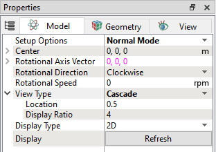
- The following conditions and parameters are available in the Properties Panel.
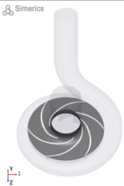
CenterRotor centre is the centre of rotation about which a rotor is rotated. It is same as rotor centre defined in the pump module, as shown in the Figure 6.54.
Rotational Axis VectorRotational axis vector is the rotational axis about which the object rotates. It is same as rotate axis defined in the pump module.
Rotational DirectionThe direction of rotation is specified as Clockwise or Counterclockwise relative to a Rotational Axis Vector.
Rotational SpeedDenotes the speed of rotation. |
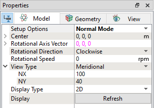
View Type
This allows to choose the plot type as meridional, or cascade as explained below.
MeridionalThe meridional planes describe the curves of the hub and shroud. The parameters required to plot are explained below.
|
|
|
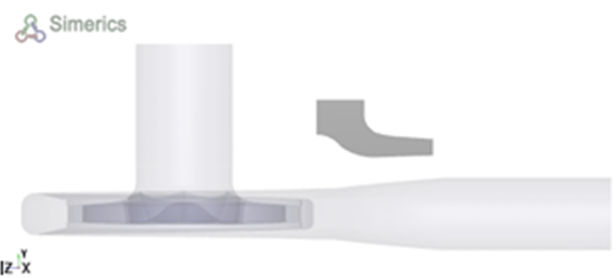
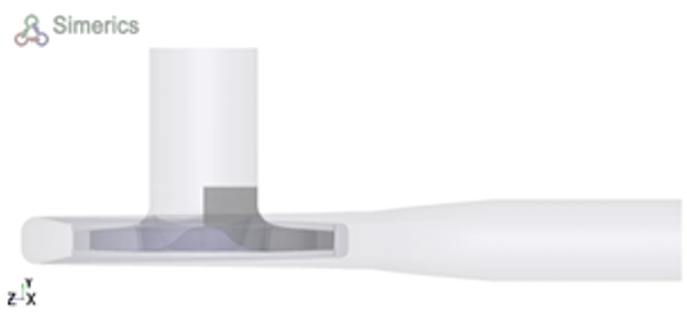
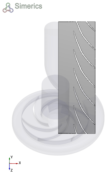
Cascade (Blade-to-Blade)The cascade planes describe the shape and size of the blades. The parameters required to plot are explained below.
|
|
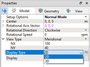
Figure 6.60 - Display Type – 2D and |