|
You are here: Fluid Machinery Templates and Tutorials > Crescent Pump > Mesher > Crescent Chamber Meshing
|
Crescent Chamber Meshing
This section explains the settings for the crescent chamber mesh generated using the Rotor Template Mesher. This involves selection of the surfaces, directional characteristics of the mesh and other advanced mesh settings.
The parameters related to Crescent meshing can be accessed by setting the Setup Options to Advanced Mode, as shown in Figure 6.295.

Inner Rotor
This is used to assign the inner rotor of the crescent pump as follows:
- Select the inner rotor surface under CAD Surfaces in the Geometric Entities Panel.
- Click Add Surfaces
 icon to the right of Inner Rotor, or click Select Inner Rotor in the Properties Panel.
Outer Rotor
This is used to assign the outer rotor of the crescent pump as follows:
- Select the outer rotor surface under CAD Surfaces in Geometric Entities Panel.
- Click Add Surfaces icon to the right of Outer Rotor, or click Select Outer Rotor in the Properties Panel.
Crescent Inside Wall
This is used to assign the crescent inside wall as follows:
- Select the crescent inside wall surface under CAD Surfaces in Geometric Entities Panel.
- Click Add Surfaces icon to the right of Crescent Inside Wall, or click Select Crescent Inside Wall in the Properties Panel.
Crescent Outside Wall
This is used to assign the crescent outside wall as follows:
- Select the crescent outside wall surface under CAD Surfaces in Geometric Entities Panel.
- Click Add Surfaces icon to the right of Crescent Outside Wall, or click Select Crescent Outside Wall in the Properties Panel.
|
Note:
|
Rotor Mesh Size
|
This allows to control the resolution of the mesh created in the crescent pumping chamber as:
|
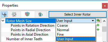

Figure 6.297 - Crescent mesh sizes
|
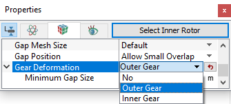
The control parameters associated with User Input (see, Figure 6.296) are:
|
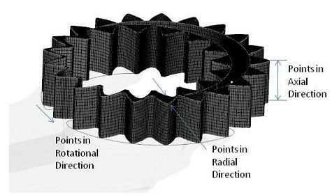
Figure 6.298 - User input mesh size-Crescent |
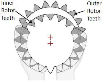
Number of Inner Teeth: Specify the number of teeth in the inner rotor.Number of Outer Teeth: Specify the number of teeth in the outer rotor. |
Figure 6.299 - Inner and Outer teeth-Crescent |
|
Note:Although the Number of Inner Teeth or Number of Outer Teeth do not affect the mesh generation, they are typically specified during the meshing operation and then automatically copied over to the Pump Configuration menu. |
Rotational Axis Vector
The direction of the axis of rotation of the inner rotor in the laboratory reference frame, specified in  coordinates.

Figure 6.300 - Rotational axis vector-Crescent
 coordinates.
 coordinates.
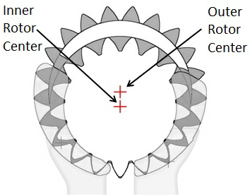
Mesh Center (0 Inner, 1 Outer)
The mesh center is a reference point used in the mesh generation process. It is the origin of the mesh coordinate system. It lies along a line connecting the inner and outer rotor centers and ranges between 0 and 1; 0 being the inner rotor center and 1 being the outer rotor center. This parameter can be used to adjust the mesh, when meshing difficulties arise. The default value of 0.5 (the average of the inner and outer rotor center coordinates) should be used for most cases (see Figure 6.295).