|
You are here: Fluid Machinery Templates and Tutorials > Crescent Pump > Model > Operating Parameters
|
Operating Parameters
The operating parameters pertaining to the Crescent template involve the time definition for the simulation, pump configuration, angular velocity definitions for pump rotation and other advanced/extended settings (see, Figure 6.314).

Figure 6.314 - Crescent model-Operating parameters
Time Definition
This provides the following ways to specify the size and number of time steps for the crescent pump simulation (see Figure 6.314).
- Revolutions: A single revolution corresponds to a pump rotation of 360 degrees. The parameters required under this Time Definition are:
- Number of Revolutions: The number of pump revolutions to be simulated.
- Time Steps Per Inner Tooth Rotation: The number of time steps taken to move the inner tooth through one pocket (angle between the tips of two inner rotor teeth).
The magnitude of the time-step size (s) and the angle of rotation (deg) depend on the Time Steps Per Inner Tooth Rotation and the Number of Inner Teeth as follows:

|
|

|
For a Time Definition of Revolutions, the Number of Time Steps is computed as follows:

|
- Number of Pockets: The amount of rotation based on the angle between two inner teeth.
- Time Steps Per Inner Tooth Rotation

Figure 6.315 - Pocket-Crescent
For a Time Definition of Pockets, the Number of Time Steps is computed as follows:

|
|
Note: The number of pockets corresponds to the number of inner teeth. |
- Time Steps Per Inner Tooth Rotation
- Number of Time Steps (in the Simulation Panel)
For a Time Definition of Total Time Steps, the Simulation Time (Duration) is computed as follows:
 |
Note:
|
Pump Configuration
This contains parameters pertaining to the geometry of the crescent pump (Figure 6.314). The inputs such as Number of Inner Teeth, Number of Outer Teeth, Inner Rotor Center and Outer Rotor Center are same as those defined in the mesher.
- Inner Rotor Shrinkage (%): Enables to shrink the inner rotor size in terms of percentage. This is used to see the effects of increased tip clearance. Figure 6.316 shows an example of shrinking the inner rotor size by 10%. Negative values of Inner Rotor Shrinkage (%) are specified to increase the size of the inner rotor.
- Outer Rotor Enlargement (%): Enables to enlarge the outer rotor in terms of percentage. This is used to see the effects of increased tip clearance. Figure 6.317 shows an example of enlarging the outer rotor by to 10%. Negative values of Outer Rotor Enlargement(%) can be specified to decrease the size of the outer rotor.
|
Note: The Inner Rotor Shrinkage (%) can be specified only once after opening Simerics-MP+. Once a non-zero value has been set, the program must be closed and reopened before any new value will take effect. For example, setting Inner Rotor Shrinkage (%) to 10%, starting a simulation, stopping the simulation, resetting Inner Rotor Shrinkage (%) to 0, and then restarting from Initial Conditions will not restore the inner rotor to its original size. |

|

|
|
Note: The Outer Rotor Enlargement(%) can be specified only once after opening Simerics-MP+.Once a non-zero value has been set, the program must be closed and reopened before any new value will take effect. For example, setting Outer Rotor Enlargement(%) to 10%, starting a simulation, stopping the simulation, resetting Outer Rotor Enlargement(%) to 0, and then restarting from initial conditions will not restore the outer rotor to its original size. |
Angular Velocity Definition
This contains parameters pertaining to the rotation of the pump. The parameters defined under the Angular Velocity Definition are: Rotational Direction, Rotational Speed and Rotational Axis Vector (see Figure 6.314).

Figure 6.318 - Angular velocity definition-Crescent
Cluster Method
This method controls the axial distribution in the inner and outer rotor using the following methods:
- Original Distribution gives a uniform cell spacing.
- Symmetric Clustering(1-2) stretches the mesh towards or away from the top and bottom of the inner rotor and outer rotor in the axial direction depending on the value entered for Cluster Mesh in Axial Direction(1-2). The values entered must be between 1.0 and 2.0.

Figure 6.319 - Cluster method-Crescent
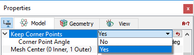
Keep Corner PointsIf this parameter is set to Yes, it snaps the mesh nodes to the original coordinates of the teeth corner points so that no clipping occurs, and the teeth keep their shape. It is set to No by default. The Corner Point Angle is used to control the angle between the tangent vector at the corner point and the vector to an adjacent corner point. If Keep Corner Points is set to Yes, the option Corner Point Angle appears with a default value of 30. |
Figure 6.320 - Keep corner points |
The other parameters Mesh Center (0 Inner, 1 Outer) and Gear Deformation are the same as defined in the crescent mesher.