|
You are here: Fluid Machinery Templates and Tutorials > External Gear Pump > Mesher > Gear chamber Meshing
|
Gear chamber Meshing
This section explains the settings for the gear chamber mesh generated using the Rotor Template Mesher. This involves selection of the surfaces, directional characteristics of the mesh and other advanced mesh settings.
The parameters related to External Gear meshing can be accessed by setting the Setup Options to Advanced Mode, as shown in Figure 6.138.

Figure 6.138 - Gear template mesher
Drive Gear
This is used to assign the drive gear as follows:
- Select the drive gear surface under CAD Surfaces in the Geometric Entities Panel.
- Click Add Surfaces
 icon to the right of Drive Gear, or click Select Drive Gear in the Properties Panel.
Drive Gear Outer Boundary
This is used to assign the portion of the boundary that surrounds the drive gear (shown in Figure 6.139) as follows:
- Select the drive gear outer surface under CAD Surfaces in the Geometric Entities Panel.
- Click Add Surfaces icon to the right of Drive Gear Outer Boundary, or click Select Drive Gear Outer Boundary in the Properties Panel.
Slave Gear
This is used to assign the slave gear as follows:
- Select the slave gear surface under CAD Surfaces in the Geometric Entities Panel.
- Click Add Surfaces icon to the right of Slave Gear, or click Select Slave Gear in the Properties Panel.
Slave Gear Outer Boundary
This is used to assign the portion of the boundary that surrounds the slave gear (shown in Figure 6.139) as follows:
- Select the slave gear outer surface under CAD Surfaces in the Geometric Entities Panel.
- Click Add Surfaces icon to the right of Slave Gear Outer Boundary, or click Select Slave Gear Outer Boundary in the Properties Panel.

Figure 6.139 - Drive and slave gear boundaries
|
Note:
|
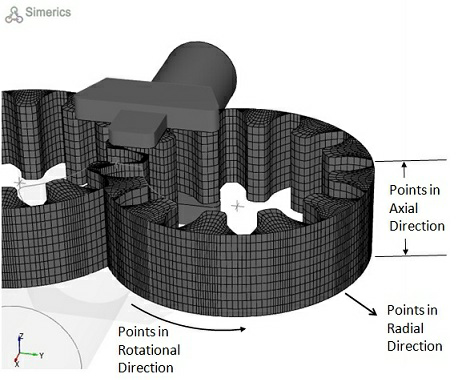
Rotor Mesh SizeThis allows to control the resolution of the mesh created in the external gear pumping chamber as:
|


|
The control parameters associated with User Input (see, Figure 6.140) are:
|
Figure 6.142 - User input mesh size-Gear |
Drive Gear Rotational Axis Vector: Specify the direction of the axis of rotation of the drive gear in the laboratory reference frame, in  coordinates.

Figure 6.143 - Rotational axis vector- Gear
Drive Gear Center:Specify the center of rotation of the drive gear in Slave Gear Center:Specify the center of rotation of the slave gear in |
 coordinates.
  coordinates.
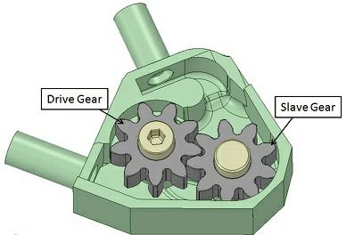
|
Note:
|
Feature Angle
This is an angle between CAD Surfaces segments. It is used to preserve the geometrical features by remembering certain CAD point segment ends, so that corners on the gear teeth are not truncated. This parameter is set to a default value of 20 degrees, and has an allowable input range between 3 and 45 degrees.
- Low values of the Feature Angle cause the grid to conform to the CAD Surfaces more closely than higher values, but the grid is less smooth internally.
- High values of the Feature Angle cause the grid to conform to the CAD Surfaces less closely than lower values, but the grid is more smooth internally.

Figure 6.145 - Gear-Feature angle