中文 English
You are here: Fluid Machinery Templates and Tutorials > External Gear Pump > Geometry and Domain

6.3.1 Geometry and Domain

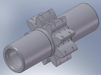
The simulation of the external gear pump requires understanding of the geometry and the fluid domain enclosed by the surfaces of the pump. The general fluid volume of the external gear pump and prerequisite steps, before taking into Simerics-MP+, are described here.

Prerequisite steps
  • The fluid volumes for the external gear pump must be created such that the gear chambers are separated from the inlet and outlet ports and from any other attached fluid volume.
  • For gear set volume, the template requires drive and slave gear surfaces to be imported (See, Figure 6.132). Since the drive gear drives the slave gear, it is important that the drive gear has to be rotated in the CAD to “contact” the slave gear. A small clearance (order of 5 microns) is required since Simerics-MP+ does not allow metal-to-metal contact.
  • The periphery of the gear set (8- shape) with tip clearance should be obtained as shown in Figure 6.133.
  • The template creates leakage gaps based on the values provided (See, Figure 6.134). Hence, the fluid volumes should be imported without clearances.
 

Figure 6.131 - Gear


Figure 6.132 - External gear surfaces


Figure 6.133 - External gear periphery surfaces


Figure 6.134 - External gear axial gap


Note:

  • The interior surface of the pump chamber volume is defined by the idealized surface of the gear teeth. Any modifications to the smooth shape of either the teeth surfaces or the outer “8-shape” can be accommodated by treating these additional fluid cavities separately and connecting them later in Simerics-MP+ with the MGI algorithm. This is true even for rotating volumes such as bevels on the teeth or the notches and cross holes in the rotor. Those fluid volumes can be added and rotated separately. For example, the .stl surfaces defining the cuts in the rotor (see, Figure 6.131) are transferred as separate entities.
  • Since the clearances in the external gear pump are typically in the order of microns, it is important that the .stl file be created with sufficient resolution and precision to allow rotation of the gear set without any interference or distortion of the geometry.


Fluid Domain

The fluid volume in an external gear pump is defined by CAD Surfaces which enclose them. The external gear pump model primarily consists of the following volumes: Inlet, Gear and Outlet as shown in Figure 6.135.

Figure 6.135 - External gear-Fluid volume

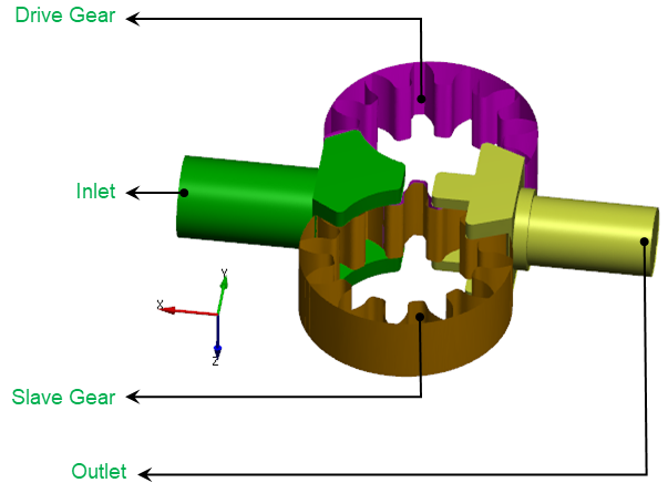
Inlet: The fluid enters the pump through the inlet boundary. Pressure is generally specified as a boundary condition at the inlet, while the other surfaces of the inlet volume are treated as walls.
Gear: The fluid volume enclosed between the gears and the shroud (8-shape). The fluid gets trapped and compressed in this volume.
Outlet: The fluid exits the pump at the outlet boundary. Pressure is generally specified as a boundary condition at the outlet , while the other surfaces of the outlet volume are treated as walls.

For an example of the external gear pump simulation, refer External Gear Pump Tutorial.


Copyright © 2023 Simerics Inc.,