6.16.1 Geometry and Domain
The modelling of multiple gears requires understanding of the geometry and the fluid domain enclosed by the surfaces. The fluid volume of the general gears and pre-requisite steps, before taking into Simerics-MP+ are described as follows:
Figure 6.882 shows, multiple spur gears externally engaged. Figure 6.883 shows planetary gear, here gears are engaged internally and externally. The general gear template has a capability to model such type of gears.
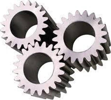
Figure 6.882 - Multiple spur gears (http://www.solidswiki.com/) |
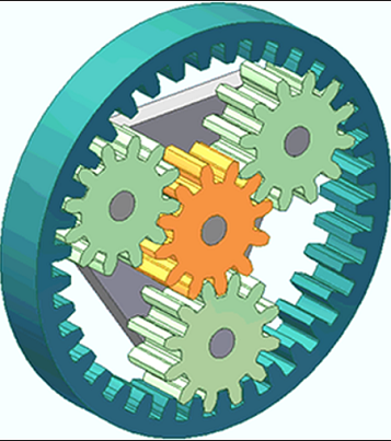
Figure 6.883 - Planetary gears (https://www.marplesgears.com/) |
Prerequisite steps
- The fluid volumes for the general gears must be created, such that the gear chambers are separated from the inlet and outlet ports and from any other attached fluid volume.
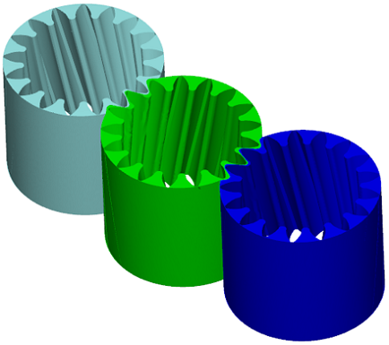
- For each gear, the template requires gear surfaces to be imported (See, Figure 6.884). Since the drive gear drives the slave gear, it is important that the drive gear must be rotated in the CAD to “contact” the slave gear. A small clearance (order of 5 microns) is required, since Simerics-MP+ does not allow metal-to-metal contact.
-
Template requires input of outer surface of each gear. There are three options to specify the details of outer surface. One option is by importing the outer surface of each gear with tip clearance, as shown in Figure 6.885. Other options are discussed in meshing section. Refer Figure 6.890.
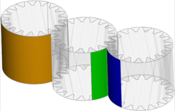
|
Note: Since the clearances in the external gear pump are typically in the order of microns, it is important that the .stl file is created with sufficient resolution and precision to allow rotation of the gear set without any interference or distortion of the geometry |
Fluid Domain
In case of pump application, the fluid volume is defined by CAD Surfaces, which enclose them. The general gear pump model primarily consists of the following Volumes: Inlet, Gears and Outlet as shown in Figure 6.886.
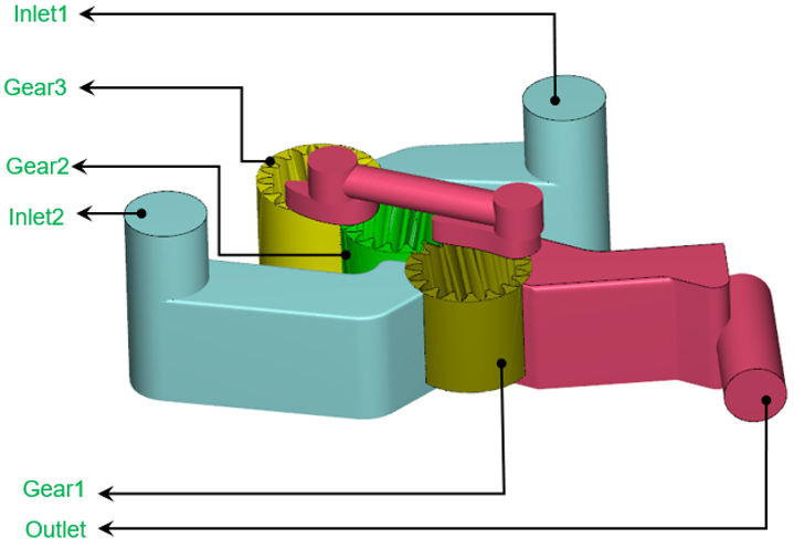
Inlet: The fluid enters the domain through the inlet boundary. Pressure is generally specified as a boundary condition at the inlet.
Gear: The fluid volume enclosed between the gears and the outer surface. The fluid gets trapped and compressed in this volume.
Outlet: The fluid exits the pump at the outlet boundary. Pressure is generally specified as a boundary condition at the outlet.
For an example of the General gear pump simulation, refer General Gear Tutorial.