|
You are here: Fluid Machinery Templates and Tutorials > General Gear > Mesher > General Gear Meshing
|
General Gear Meshing
Gear Parameters
Gear Rotational Axis Vector
Specify the direction of the axis of rotation of the drive gear in the laboratory reference frame, in  coordinates.

Figure 6.889 - Rotational axis vector- General Gear
Add a Gear
This is used to assign the type of the gear. Choose between Internal Gear and External Gear.
The control parameters associated with Internal Gear/ External Gear are below.
Gear Name
Provide the gear name under Gear Name in Gear 1 list.
Gear Center
Provide the center of gear rotation in  coordinates, also the center of the gear container cylinder. Refer Figure 6.889.
Gear Surfaces
This is used to assign the gear as follows:
- Select the gear1 surface under CAD Surfaces in the Geometric Entities Panel.
- Click Add Surfaces
 icon to the right of Gear Surfaces in the Properties Panel.
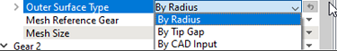
Outer Surface Type
|
Template requires input for outer surface of each gear. User can specify the outer surface by following options.
|
Number of Teeth
Specify the number of repeating geometry unit (gear teeth) on the gear.
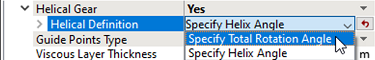
Helical Gear
|
Select Yes to model helical gear and specify corresponding parameters. The template supports two different Helical Definition types: |
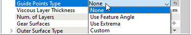
Guide Points Type
|
Guide Points are points that stay relatively stationary to the gear (i.e. rotate with the gear) during the gear movement. Guide Points prevent points moving from one gear tooth to the next gear tooth, therefore ensuring the positivity of volume in helical gear mesh. This feature has three options. Use Feature Angle, Use Extrema and Custom. |
- Use Feature Angle: Set any corner points, where the angle is greater than the set value as a guide point. Most common option for angular gear shape.
- Use Extrema: Use the points at the local maximum radius as guide points, can be used for smooth shaped gear/rotor.
- Custom: Find the nearest points on the gear from each point entered by the users and use them as guide points. Meanwhile, repeat the points N times around the gear and define them as guide points (N being the number of gears set by the user). The user must input the guide point with respect to the lower outline shape of gear in case of a helical gear.
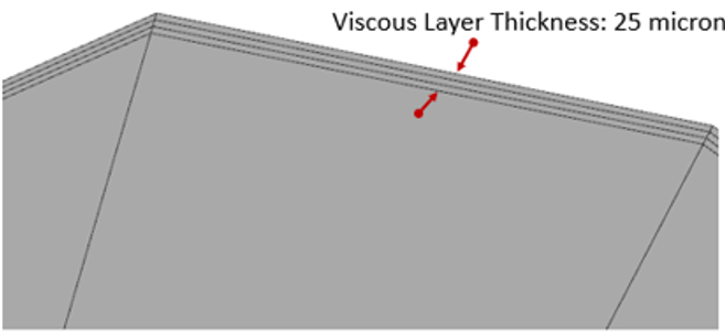
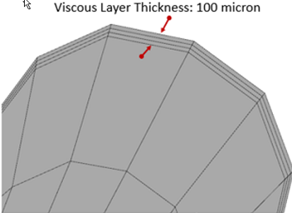
Viscous Layer Thickness
It is the total thickness of viscous layer. Figure 6.893 shows the viscous layer thickness with 25 micron and Figure 6.894 shows the viscous layer thickness with 100 microns.
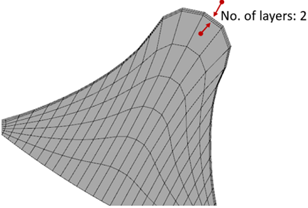
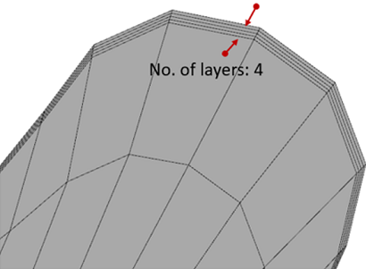
Number of Layers
Specify number of cells (not nodes) in the viscous layer. Figure 6.895 shows 2 layers in the viscous thickness and Figure 6.896 shows 4 layers in the viscous thickness.
Mesh Reference Gear
By default, this is selected as Yes for first gear.


Specify Total Rotational Angle
Specify the total rotation angle between bottom and top surface (axial direction). The value is signed, it is positive when the rotation direction is the same as what is defined by the right-hand rule and the rotational axis vector.
Calculation of Total Rotational Angle
- Pick one feature in the gear teeth, as shown Figure 6.899.
- Mark two points at top and bottom surface for the same feature. Refer Figure 6.900.
- Then, from top view, connect two points to the center using two lines and measure the angle between the lines, i.e. “Total Rotation Angle”. Refer Figure 6.901.
- From bottom to top, if rotated in counter-clockwise, the angle is positive. Otherwise, the angle is negative.
For each pair of helical gears, the total rotational angle must have opposite sign. One is Positive and other one is Negative.
Value of Total Rotational angle multiply by the number of teeth is constant.
Example: In a pair of two meshing Helical gears, if one gear contains 10 teeth with +10° total rotational angle and other gear contains 20 teeth, then total rotational angle for other gear must be 
|
|

|

|

Specify Helix Angle
This allows to specify the angle between the gear teeth axial inclination and the gear axis. During mesh generation, the Helix Angle (see, Figure 6.902) is used to specify the correct slant of the rotor whereas, the CAD Surfaces are used as bounds for the mesh to obtain a water-tight volume.

|
The control parameters associated with User Defined (see, Figure 6.903) are:
|
Once the parameters for meshing are defined, click Build General Gear Mesh in the Geometry Tab of the Properties Panel. The general gear mesh is created and added under Built Meshes, and the corresponding Volumes are generated in the Geometric Entities Panel. Also, General Gear module is added to the Model Panel.