|
You are here: Automotive Templates and Tutorials > Automotive Tutorials > Planetary Gearbox Tutorial > Building the Mesh
|
Building the Mesh
This section describes the step-by-step procedure to prepare the mesh for the planetary gearbox simulation. The Rotor Template Mesher is used for creating the gear mesh for sun, ring, and planets and the General Mesher is used for carrier, cavity and housing.
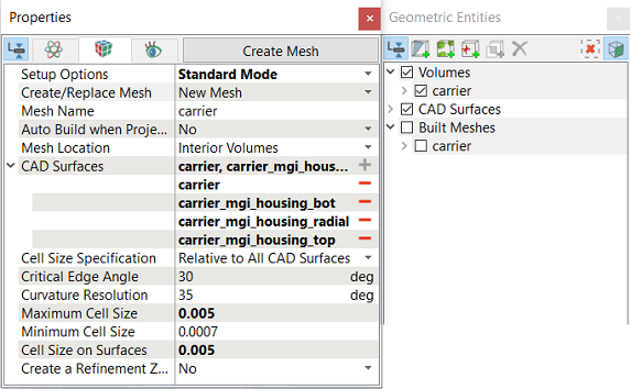
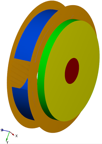
Cavity
|
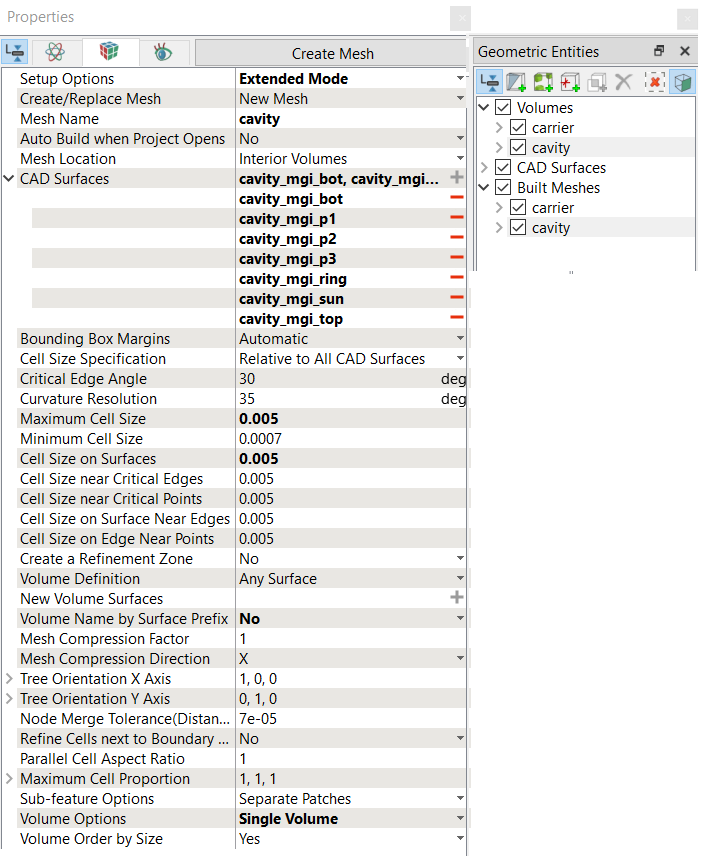
Figure 7.190 - Cavity mesh settings
|
Housing
|
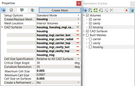
Figure 7.191 - Housing mesh settings |
Planetary GearsGeneral Parameters
Gear 1: Sun Gear Parameters
Gear 2: P1 mesh Parameters
Gear 3: P2 mesh Parameters
|
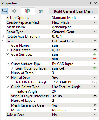
Figure 7.192 - Gear1 mesh settings
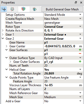
Figure 7.193 - Gear2 mesh settings
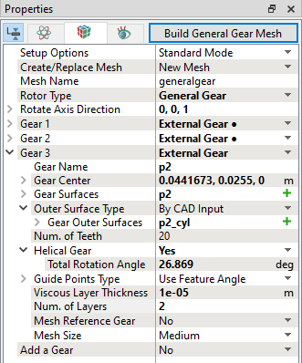
Figure 7.194 - Gear3 mesh settings |
Gear 4: P3 mesh Parameters
Gear 5: Ring Gear Parameters
|
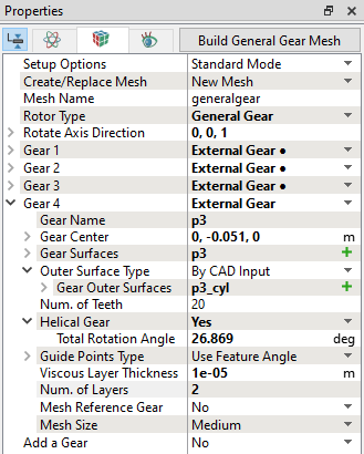
Figure 7.195 - Gear4 mesh settings 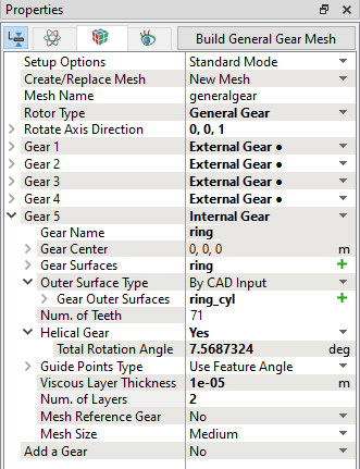
Figure 7.196 - Gear5 mesh settings |
Build General Gear MeshAfter specifying all planetary gear mesh parameters, generate mesh as follows:
|
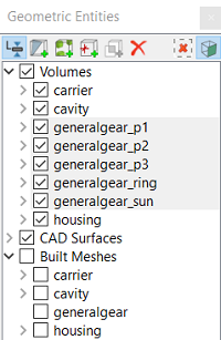
Figure 7.197 - Planetary Gear volumes |
The mesh created for the fluid domain is shown below.
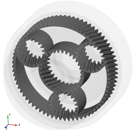
Figure 7.198 - Gear mesh |
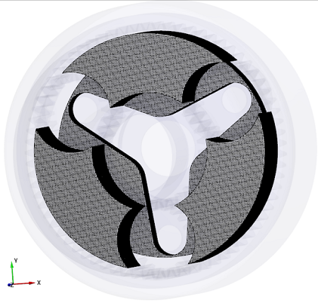
Figure 7.199 - Cavity and Carrier mesh |
|
Note: The mesh can be edited/replaced by selecting required volume under Built Meshes and modify the mesh parameters in the Properties Panel. Click Create Mesh to reflect the changes. |
Default MGI Creation in Template Mesher
- The Rotor Template Mesher creates interfaces between the set of gears automatically.
- Six Mismatched Grid Interfaces (MGIs), MGI01 to MGI06 are created interfacing the sun gear, planet gears and ring gear under Volumes.
-
In these MGIs, inline expressions are used to calculate projection tolerance, which is important to connect the interfaces. It is recommended not to change these settings.
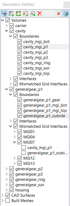
Create interfacesIn this section, the Mismatched Grid Interfaces (MGIs) are generated between boundaries for connected volumes. The steps to create the MGIs are shown below:
A group display of entities can be viewed using the Group Entities by Volumes/Types
Table 7.4 - Creating interfaces
The new entities are created under MGI in Volumes (refer, Figure 7.200). |
| ´ | Note: If MGIs are created by connecting the wrong boundaries, delete the created MGIs by clicking on Delete Selected Geometric Entity |