|
You are here: Automotive Templates and Tutorials > Automotive Tutorials > Planetary Gearbox Tutorial > Defining Physics and Conditions
|
Defining Physics and Conditions
The physics and conditions are specified as follows:
Adding Modules
|
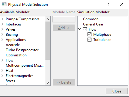
Figure 7.202 - Adding modules
|
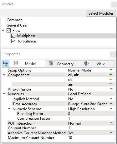
Multiphase
|
Figure 7.203 - Multiphase operating parameters
|
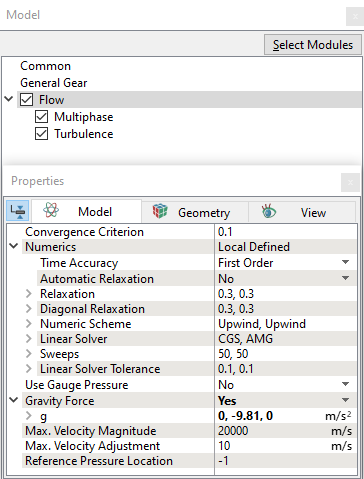
Flow
|
Figure 7.204 - Flow operating parameters |
General Operating Parameters
|
Figure 7.205 - Operating parameters |
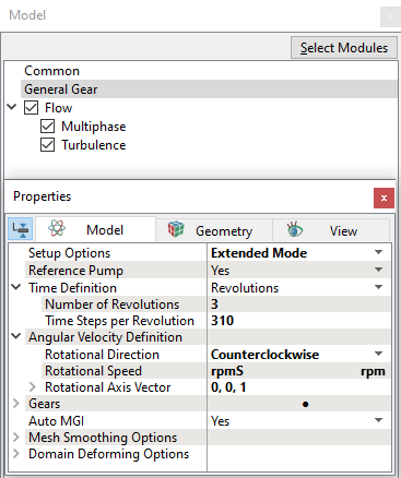
| ´ | Note: Provide speed and angular velocity definition parameters with respect to sun gear, as it is set as main gear. |
Boundary Conditions
Gear Conditions
In this simulation, Ring gear is held stationary, speed is set as 0 rpm (rpmR) and sun gear rotates at 600 rpm (rpmS). Both of these conditions are provided using expressions.
The Speed ratio is set as zero for Gear 2, Gear 3, Gear 4, and Gear 5 in the general gear module.
The translation/rotation for planet gears (Gear 2, Gear 3, Gear 4) is provided using additional movement option in the gear module by calling user expressions written under global expression editor. Refer Global expressions for expression and speed relations.
|
Enter the parameters as follows:
|
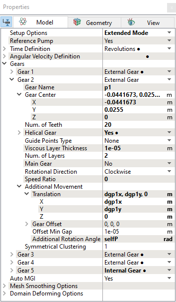
Figure 7.206 - General gear module parameters |
| Note: The gear boundary conditions are assigned automatically by the Rotor Template Mesher. |
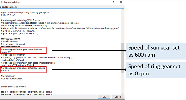
Global Expression
# initial oil level VOFoil = (y<-0.03)? 1:0 VOFair = 1 - VOFoil # sun gear total angle # -17.33483871 # planet gear total angle # 26.869 # ring gear total angle # 7.568732394 # rotating axis axis = [0,0,1] # sun gear center Scenter = [0, 0, 0] # planet1 center gp1c = [-0.0441673, 0.0255, 0] # planet2 center gp2c = [0.0441673, 0.0255, 0] # planet3 center gp3c = [0, -0.051, 0] # S sun gear, P planetary gear, R ring gear, C carrier # number of teeth # sun gear zS = 31 # planetary gear zP = 20 # ring gear zR = 71 # gear teeth relationship for any planetary gear system # zR = 2*zP + zS # rotation speed relationship (Willis Equation) # this relationship connects the rotatiton speeds of sun, planetary, ring gears and carrier # these two equations will be satisfied simutanously # reference link https://www.tec-science.com/mechanical-power-transmission/planetary-gear/willis-equation-for-planetary-gears/ # rpmP*zP = rpmC*(zP+zS) - rpmS*zS (1) # rpmR*zR = rpmC*(zR+zS) - rpmS*zS (2) #### scenario 1#### # rpmS is an input # rpmR is zero (stationary) ################ # rotation speed for sun gear, conterclockwise rpmS = 600 # rotation speed for carrier # assuming ring gear is stationary, rpmC can be derived based on relationship (2) rpmC = zS/(zS + zR)*rpmS # rotation speed for planetary gear, based on relationship (1) rpmP = (rpmC*(zP+zS) - rpmS*zS)/zP # rotation speed for ring gear, stationary ring gear rpmR = 0 # for translation # Carrier rotation speed angle = rpmC*2*pi/60*time dgp1x = (gp1c.x*cos(angle) - gp1c.y*sin(angle)) - gp1c.x dgp1y= (gp1c.x*sin(angle) + gp1c.y*cos(angle)) - gp1c.y dgp2x = (gp2c.x*cos(angle) - gp2c.y*sin(angle)) - gp2c.x dgp2y= (gp2c.x*sin(angle) + gp2c.y*cos(angle)) - gp2c.y dgp3x = (gp3c.x*cos(angle) - gp3c.y*sin(angle)) - gp3c.x dgp3y= (gp3c.x*sin(angle) + gp3c.y*cos(angle)) - gp3c.y # for cavity volume remesh newx =x*cos(angle) - y*sin(angle) newy =x*sin(angle) + y*cos(angle) # self rotation angle for planetary gears selfP = rpmP*2*pi/60*time # self rotating angle for ring gear selfR = rpmR*2*pi/60*time
|
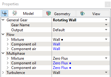
| Note: Select Yes for Power under Flow output list for the carrier, and all gear boundaries. |
Carrier Volume condition
|
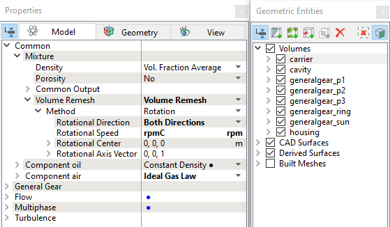
Figure 7.209 - Carrier volume condition |
Cavity Volume condition
|
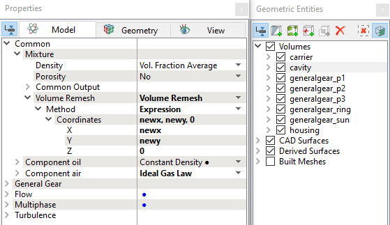
Figure 7.210 - Cavity volume condition
|
Fluid properties
Component oil:
Component air:
Initial Condition:
|
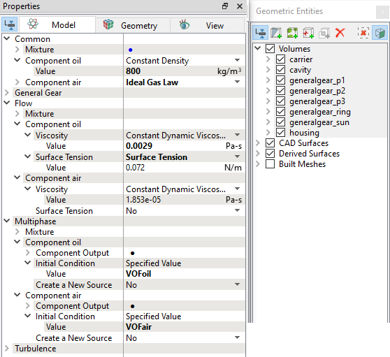
Figure 7.211 - Fluid properties |
| Note: Select Yes for Mass Fraction, Volume Fraction, Phase Mass and Phase Volume under Component Output list for the Component oil and Component air list. |