|
You are here: Fluid Machinery Templates and Tutorials > Gerotor Pump > Mesher > Gerotor chamber Meshing
|
Gerotor chamber Meshing
This section explains the settings for the gerotor chamber mesh generated using the Rotor Template Mesher. This involves selection of the surfaces, directional characteristics of the mesh and other advanced mesh settings.
The parameters related to Gerotor meshing can be accessed by setting the Setup Options to Advanced Mode, as shown in Figure 6.71

Inner Rotor
This is used to assign the inner rotor of the gerotor as follows:
- Select the inner rotor surface under CAD Surfaces in the Geometric Entities Panel.
- Click Add Surfaces
 icon to the right of Inner Rotor, or click Select Inner Rotor in the Properties Panel.
Outer Rotor
This is used to assign the outer rotor of the gerotor as follows:
- Select the outer rotor surface under CAD Surfaces in Geometric Entities Panel.
- Click Add Surfaces icon to the right of Outer Rotor, or click Select Outer Rotor in the Properties Panel.
|
Note: The boundary conditions are automatically set by the template for the assigned surfaces. |
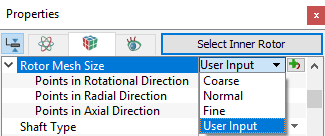
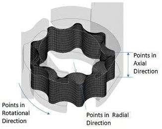
Rotor Mesh SizeThis allows to control the resolution of the mesh created in the gerotor pumping chamber as:
|

|
The control parameters associated with User Input (see, Figure 6.74) are:
|
||||
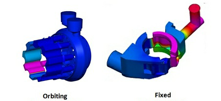
Shaft TypeThe template supports two different shaft types:
|
Figure 6.75 - Shaft type- Gerotor |
 coordinates.
 coordinates.
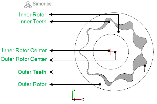
|
Note: Although the Number of Inner Teeth or Number of Outer Teeth do not affect the mesh generation, they are typically specified during the meshing operation and then automatically copied over to the Pump Configuration menu. |
Rotational Axis Vector
The direction of the axis of rotation of the inner rotor in the laboratory reference frame, specified in  coordinates.

Figure 6.77 - Rotational axis vector-Gerotor
Meshing Method
This provides the following two methods:
- Radial: The mesh lines radiate from the rotor center (intersecting circumferential mesh lines) and terminate at points on the outer rotor outline. This is the default method of meshing.
- Linear: This is designed to mesh rotors with complex outlines, where the mesh nodes are distributed on the inner/outer rotor outline directly. It is an advanced method, currently only recommended if meshing difficulties arise using the Radial method. Once Linear meshing is selected, Smooth Rotor Mesh is also activated since it usually requires a certain amount of smoothing to remove any negative interior cell volumes which might be created. The Linear method is better suited for gerotor outlines shaped less smoothly in the circumferential direction (i.e. containing protrusions or indentations).

Figure 6.78 - Meshing method-Gerotor
Smooth Rotor Mesh
This allows to improve the gerotor mesh using a mesh smoothing algorithm, which maximizes cell face orthogonality and optimizes the cell density distribution.

Figure 6.79 - Smooth Rotor Mesh
- Max Iterations: Specifies the number of iterations the smoothing algorithm has to run for. The default value is 15, usually optimal for most cases. However, user can adjust this to capture any desirable mesh characteristics which could prove useful for a specific application. To illustrate the effect of this value, as shown in Figure 6.80, the choice of Max Iterations = 100 proved to be excessive, since the mesh quality was reduced compared to the mesh created using the value Max Iterations = 15.
- Relaxation (0 < r < 2): Specifies what percentage (i.e. 70% = 0.7 for relaxation value) of the calculated node (cell volume corner point) position displacement increment calculated during the smoothing process is used for the final mesh point locations at a given time-step. Low values of relaxation show that the resulting mesh is almost indistinguishable from a mesh made using Meshing Method: Radial. A relaxation value of 0.5 creates a mesh that appears to be an average of a mesh created using the default Radial meshing method and a mesh created using the Linear meshing method. The default relaxation value of 1.0 (see, Figure 6.81).
|
|

|

|

Helix Angle Rotor
This allows to specify the angle between the rotor axial inclination and the rotor axis. It can be specified for either the Inner Rotor or Outer Rotor. During the mesh generation, the Helix Angle is used to specify the correct slant of the rotor whereas, the CAD Surfaces are used as bounds for the mesh to obtain a water-tight volume.The helix angle value is prescribed under Angle.
