|
You are here: Fluid Machinery Templates and Tutorials > Scroll Compressor > Model > Operating Parameters
|
Operating Parameters
The operating parameters pertaining to the Scroll template involve the time definition for the simulation, pump configuration, angular velocity definitions for pump rotation and other advanced/extended settings (see, Figure 6.799).

Figure 6.799 - Scroll model-Operating parameters
Time Definition
This provides the following ways to specify the size and number of time steps for the scroll compressor simulation (see Figure 6.799):
- Revolutions: A single revolution corresponds to a compressor rotation of 360 degrees. The parameters required under this Time Definition are:
- Number of Revolutions: The number of compressor revolutions to be simulated.
- Time Steps Per Revolution: The number of time steps for each revolution of the compressor.
- Time Steps Per Revolution
For a Time Definition of Total Time Steps, the Number of Time Steps may be specified directly in the Simulation Panel.
|
Note: If the Number of Time Steps is displayed in Blue, it means that it is set and controlled elsewhere and cannot be changed in the context of the Simulation Panel. |
|
|
Note: The setting of the Time Definition in the Properties Panel of the Model Tab and in the Simulation Panel are slaved to each other, such that changing the value in one panel, changes the value in the other. |
|
|
Note: If multiple templates are active, the Scroll module must be set as the Reference Pump for the Time Definition option to be displayed. |
Pump Configuration
This contains parameters pertaining to the geometry of the scroll compressor (see Figure 6.799). The inputs such as Stator Center, Rotor Center, Rotation Radius Shrinkage (%) are same as those defined in the mesher.
Angular Velocity Definition
This contains parameters pertaining to the rotation of the compressor. The parameters defined under the Angular Velocity Definition are: Rotational Direction, Rotational Speed and Rotational Axis Vector (see for options).

Figure 6.800 - Angular velocity definition
|
Note: A variable speed is specified by using the Expression Editor in the Rotational Speed. |
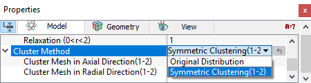
Cluster MethodThis method controls the axial and radial grid distribution in the rotor and stator.
The other parameter, Smooth Rotor Mesh is the same as defined in the scroll mesher. |
Figure 6.801 - Cluster method-Scroll |