|
You are here: Fluid Machinery Templates and Tutorials > Scroll Compressor > Scroll Compressor Tutorial > Building the Mesh
|
Building the Mesh
This section describes the step-by-step procedure for preparing the mesh for the scroll compressor. The Rotor Template Mesher is used for creating the scroll chamber mesh and the General Mesher is used for creating the mesh for the inlet, outlet and the scroll external volume.
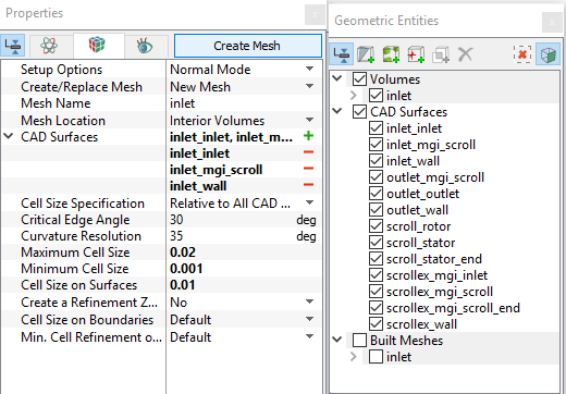
Scroll Chamber Mesh
|
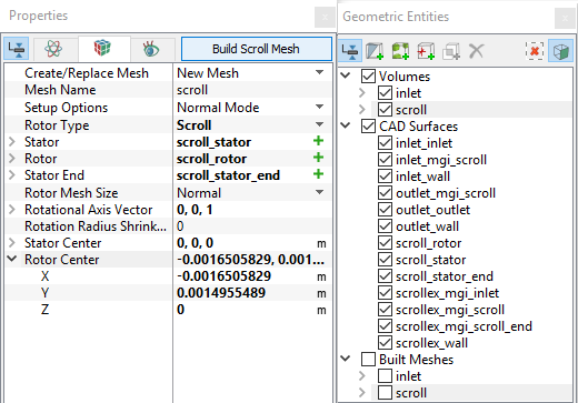
Figure 6.812 - Scroll chamber mesh settings |
Outlet Mesh
|
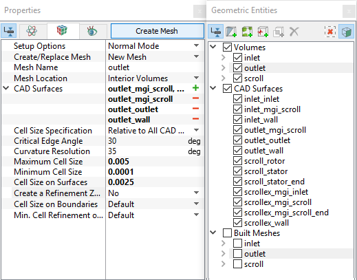
Figure 6.813 - Outlet mesh settings |
Scroll External Volume Mesh
|
Figure 6.814 - Scrollex mesh settings |
| ´ | Note: The mesh can be edited/replaced by selecting it under Built Meshes, and modify the mesh parameters in the Properties Panel. Click Create Mesh to reflect the changes. |
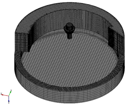
The mesh created for the fluid domain is shown below.
|
Figure 6.815 - Inlet, Outlet and Scroll external volume mesh |
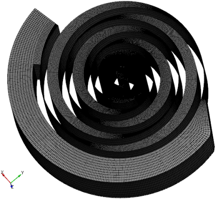
Figure 6.816 - Scroll mesh |
Create interfaces
In this section, the MGIs are generated between boundaries. It connect the various volume surfaces to the appropriate adjacent volume surfaces
The steps to create the MGIs are shown below:
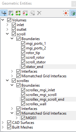
- Geometric Entities Panel > Volumes > Boundaries, select Boundaries as shown in Table 6.42.
- Click Connect Selected Boundaries via MGI
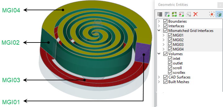
 icon to create the MGI entities (see, Figure 6.817).
A group display of entities can be viewed using the Group Entities by Volumes/Types ![]() icon inGeometric Entities Panel toolbar.
icon inGeometric Entities Panel toolbar.
| Connecting interfaces | Boundaries | Entity |
|---|---|---|
| Scroll external and scroll | Scrollex_mgi_scroll_end and stator_end | MGI01 |
| Scroll and scroll external | scroll_stator and scrollex_mgi_scroll |
MGI02 |
| Inlet, scroll and scroll external | Inlet_mgi_scroll, mgi_ports_2 and scrollex_mgi_inlet | MGI03 |
| Scroll and outlet | Mgi_port_1 and outlet_mgi_scroll | MGI04 |
Table 6.42 - Creating interfaces
An entity MGI02 is created but the Interface was not created because the default parameters associated the MGI02 were too restrictive to find the connection. These parameters can be relaxed to enable the MGI logic to create the correct fluid-fluid connection.
The steps to create the Interface for MGI02 are shown below:
- Select MGI02 under Geometric Entities Panel.
- Enter the following parameters under Properties Panel > Model Tab:
- Projection Tolerance: 0.1
- Normal Tolerance: 89
- Face Normal Tolerance: 5
- Face Distance Tolerance: 0.0001
With the specified tolerances, the MGI02 interface is successfully created. For more details on projection tolerance refer manual.
The new entities are created under MGI > Volumes (see, Figure 6.818).
|
Note: If MGIs are created by connecting the wrong boundaries, delete the created MGIs by clicking on Delete Selected Geometric Entity |