Leakages
This section explains the settings for specifying the leakages in the vane chamber mesh. generated using the Rotor Template Mesher.
The parameters related to Vane leakages can be accessed by setting the Setup Options to Advanced Mode.
|
Note: If the leakage has an arbitrary shape, it can be modelled using general mesher. |
Side Gap Option
The two types of side gaps are:
A) Uniform Side Gaps
Description
Enables the creation of two Axial Clearance Gaps, each with the same clearance above and below the vane rotor volume.

Figure 6.208 - Uniform side gap (Vane) - Properties panel
The parameters associated with a Uniform Side Gap are:
Gap Outline ShapeThis provides the option of selecting either Circle from Input Radius or Same as Chamber Wall as the method used to determine the outer circumferential boundary of the axial side gaps.
|
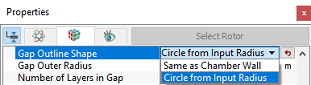
Figure 6.210 - Gap outline shape |
|
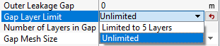
Gap Layer LimitAllows to limit number of mesh layers under Limited to 5 Layers option and allows to add more than 5 mesh layers in gaps under Unlimited option, as shown in Figure 6.211. This option gives user additional control for Number of Layers in Gap, as shown in Figure 6.211. When the Limited to 5 Layers option (the default option) is selected, user can only set up to 5 layers for Number of Layers in Gap. When Unlimited option is selected, user can set any number of layers for Number of Layers in Gap.
|
|
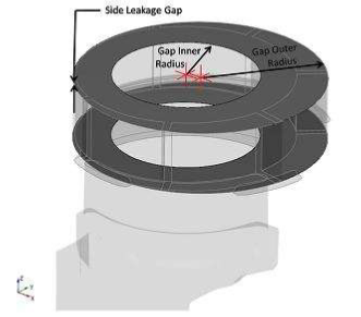
Note: The inner radius and outer radius of the Side Leakage Gap should correspond to the actual leakage gap. In any case, the minimum value that can be input for Gap Inner Radius must be greater than 0 (a small value will work) and the maximum must be less than the Gap Outer Radius. |
B) Nonuniform Side Gaps
This option enables creation of Axial Leakage Gaps for which the top and bottom gap clearances and number of mesh layers can be specified independently of one another. This is an advanced option. The other inputs define in Nonuniform side gaps i.e. Gap Inner Radius and Gap Outline Shape are same as Uniform side gap.

The parameters associated with a Nonuniform Side Gap are:
Bottom Leakage Gap: Allows to set the gap height of the side (axial) clearance below the pumping chamber of theVane Pump.
Top Leakage Gap:Allows the user to set the gap height of the side (axial) clearance above the pumping chamber of theVane Pump.
No. of Layers in Bottom Gap: Allows specification of the number of mesh layers within the Bottom Leakage Gap.
No. of Layers in Top Gap: Allows specification of the number of mesh layers within the Top Leakage Gap.
|
Note: Dynamic, nonuniform side (axial) clearance geometries can be incorporated into Simerics-MP+ using volume remesh in conjunction with tables and/or the Expression Editor. |
|
Note: Non-zero values of Bottom Leakage Gap and Top Leakage Gap will cause these gap volumes to be created during the Rotor Template Mesher operation. Two gaps, each with their respective thicknesses, are added. They are added above and below the vane rotor volume and automatically connected to the vane rotor volume via MGI. |
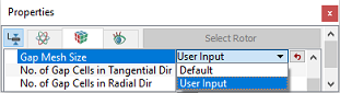
Gap Mesh SizeTo control the mesh cell size and distribution in the Side Leakage Gap (axial gap). The Gap Mesh Size has two options:
|
Figure 6.213 - Gap mesh size - Vane |
Gap Position
This allows to select the position of Side Leakage Gap (axial gap) where it is inserted in between the rotors and the ports. The options to specify the Gap Position are: Allow Small Overlap, Shrink Rotor and Gap Outside Rotor (see, Figure 6.212).
- Allow Small Overlap: The rotor is shrunk on both ends to accommodate the gap, with a quarter of a cell overlap at the boundaries. This option can be used when there is no gap between the rotor and ports in CAD.
- Shrink Rotor: The rotor is shrunk as needed on both ends to accommodate the gap with no overlap at the boundaries. This option is used when there is no gap between the rotor and ports in CAD.
-
Gap Outside Rotor: The rotor is not shrunk, and the gap is placed between the rotor and ports. This option requires that space for the gap has already been created in CAD.