中文 English
You are here: Tutorials > Cavitation Over an Orifice > Setting up the model > Building the Mesh

Building the Mesh

This section describes the step-by-step procedure for preparing the mesh that contain Orifice surfaces. The mesh is created using the General Mesher . The settings for the mesh generation are explained in the following steps:

Orifice
  1. Select General Mesher in the Mesh Panel.
  2. Select CAD Surfaces Orifice_inlet, Orifice_outlet and Orifice_wall in the Geometric Entities Panel.
  3. Click Add Surfaces of the CAD Surfaces in the Properties Panel.
  4. Enter Maximum Cell Size as 0.005, Minimum Cell Size as 0.001 in the Properties Panel.
  5. Select Cylindrical Zone under Create a Refinement Zone drop-down list.

  6. Enter the parameter under the Refine Zone Options list as follows.

    • Cell Size: 0.0025
    • Top Circle Center: 0.014, 0, 0
    • Bottom Circle Center: 0.032, 0, 0
    • Zone Radius: 0.006
  7. Click Create Mesh. A new mesh Orifice is created under Built Meshes in the Geometric Entities Panel.
  8. The meshed volume Orifice is generated under Volumes.
 

Figure 11.240 - Orifice mesh settings


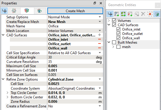
  Note: Mesh is refined near the contraction region to capture the cavitation bubble.

The created mesh is shown below:

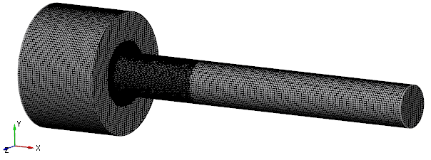
Figure 11.241 - Volume mesh


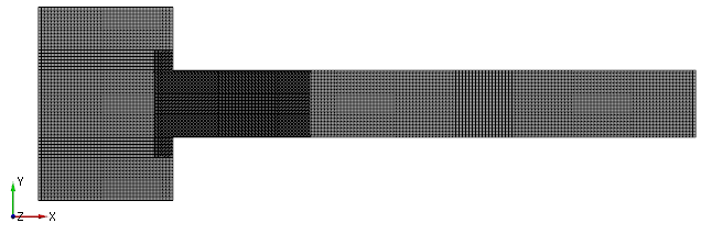
Figure 11.242 - Cross-sectional view


Copyright © 2023 Simerics Inc.,