Defining Physics and Conditions
The physics and conditions are specified as follows.
Add Modules
- Click Select Modules in the Model Panel. The Physical Model Selection dialog box opens.
- Select Flow under Available Modules list and click Add.
- Select Heat under Available Modules list and click Add.
-
Click Close to close the Physical Model Selection dialog box.
|
|
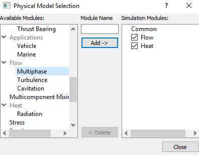
Figure 11.80 - Adding modules
|
Properties
Disk
- Select disk under Volumes in the Geometric Entities Panel.
-
Enter 2400 kg/m3 for Value under the Density drop-down list in the Model Tab of Properties Panel.
-
Select Blanked from the State drop down list under Flow.
- Enter 1.5 W/m-K for Conductivity in the Conductivity list under Heat.
-
Enter 1.07 J/kg-K for Capacity under Heat.
|
|
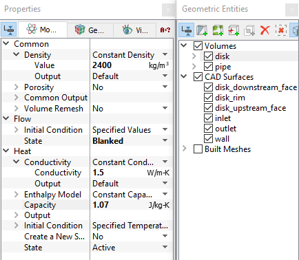
Figure 11.81 - Properties for disk
|
| |
Note: Setting the Flow > State to Blanked turns off the solution of the flow in that volume and, in effect, creates a solid.
|
Pipe
- Select pipe under Volumes in the Geometric Entities Panel.
-
Enter 998 kg/m3 for Value under the Density in the Model Tab of Properties Panel.
-
Enter 0.001 Pa-s for Value in the Viscosity list under Flow .
- Enter 0.7 Pa-s for Prandtl Number in the Conductivity list under Heat.
-
Enter 4180 J/kg-K for Capacity under Heat.
|
|
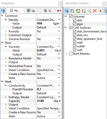
Figure 11.82 - Properties for pipe
|
Create a heat source
- Select disk under Volumes in the Geometric Entities Panel.
-
Select Total Heat Source from Create a New Source drop-down list under Heat in the Model Tab of Properties Panel.
-
Enter 60 W for Value in the Source list under Heat.
|
|
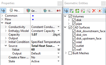
Figure 11.83 - Heat source
|
Boundary conditions
The boundary conditions are specified as follows:
Inlet
- Select inlet from the Boundaries list in the Geometric Entities Panel.
- Select Specified Velocity from the Flow drop-down list in the Model Tab of Properties Panel.
-
Enter 0, 0, 0.001 m/s for Velocity in the Method list under Flow.
|
|
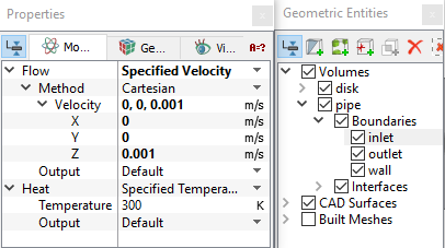
Figure 11.84 - Inlet conditions
|
Outlet
- Select outlet from the Boundaries list in the Geometric Entities Panel.
- Select Specified Pressure Outlet from the Flow drop-down list in the Model Tab of Properties Panel.
- Enter 0 Pa for Pressure under Flow list.
- Select User Specified from the Back Flow Option and enter 300 K for the Temperature under Flow.
|
|
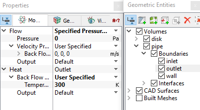
Figure 11.85 - Outlet conditions
|
Wall
- Select wall from the Boundaries list in the Geometric Entities Panel.
- Select Specified Temperature from the Heat drop-down list in the Model Tab of Properties Panel.
-
Enter 320 K for Temperature under Heat.
|
|
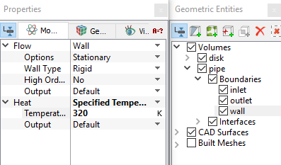
Figure 11.86 - Wall conditions
|