Building the Mesh
This section describes the step-by-step procedure for preparing the mesh for the mixing tank model that contains stator and rotor. The mesh is created using the General Mesher.
Rotor
- Select General Mesher in the Mesh Panel.
- Select CAD Surfaces mixingtank_rotor, mixingtank_rotor_mgi_statorbot, mixingtank_rotor_mgi_statorside and mixingtank_rotor_mgi_statortop in the Geometric Entities Panel.
- Enter Maximum Cell Size as 0.01, Minimum Cell Size as 0.001, Cell Size on Surfaces as 0.01 in the Properties Panel.
- Click Create Mesh. A new mesh mixingtank_rotor is created under Built Meshes in the Geometric Entities Panel.
- To refine the interfaces, click mixingtank_rotor from Built Meshes and select mixingtank_rotor_mgi_statorside from CAD Surfaces.
- Select User Input from Cell Size on Boundaries drop-down list and enter 0.005 for Size in the Properties Panel. Click Create Mesh to update mixingtank_rotor under Built Meshes in the Geometric Entities Panel.
- The meshed volume mixingtank_rotor is generated under Volumes.
|
|
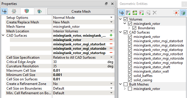
Figure 11.283 - Rotor mesh settings
|
Stator
- Select General Mesher in the Mesh Panel.
- Select CAD Surfaces mixingtank_stator_mgi_rotorbot, mixingtank_stator_mgi_rotorside, mixingtank_stator_mgi_rotortop, mixingtank_stator_shaft and mixingtank_stator_wall in the Geometric Entities Panel.
- Enter Maximum Cell Size as 0.01, Minimum Cell Size as 0.001 and Cell Size on Surfaces as 0.01 in the Properties Panel.
- Click Create Mesh. A new mesh mixingtank_stator is created under Built Meshes in the Geometric Entities Panel.
- To refine the interfaces, click mixingtank_rotor from Built Meshes and select mixingtank_rotor_mgi_statorside from CAD Surfaces.
- Select User Input from Cell Size on Boundaries drop-down list and enter 0.005 for Size in the Properties Panel. Click Create Mesh to update mixingtank_rotor under Built Meshes in the Geometric Entities Panel.
- The meshed volume mixingtank_stator is generated under Volumes.
|
|
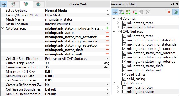
Figure 11.284 - Stator mesh settings
|
The mesh created for the fluid domain is shown below.
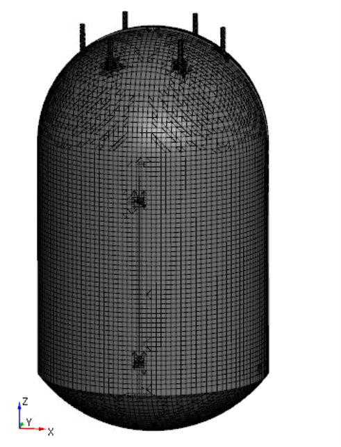
Figure 11.285 - Full Mesh view
|
|
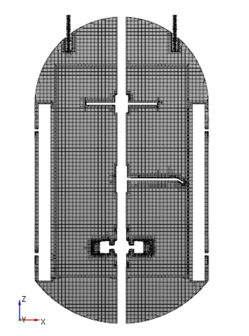
Figure 11.286 - Cross-sectional view
|
Create interfaces
In this section, the Mismatched Grid Interfaces (MGI) are generated between boundaries.
The steps to create the MGI is as follows:
- Geometric Entities Panel > Volumes > Boundaries, select entities shown under boundaries (see, Table 11.12).
- Click Connect Selected Boundaries via MGI
 icon to create the MGI entities (see, Figure 11.287).
A group display of entities can be viewed using the Group Entities by Volumes/Types  icon at Geometric Entities Panel toolbar.
| Stator Bottom and Rotor Bottom |
mixingtank_stator_mgi_rotorbot, mixingtank_rotor_mgi_statorbot |
MGI01 |
| Stator Side and Rotor Side |
mixingtank_stator_mgi_rotorside, mixingtank_rotor_mgi_statorside
|
MGI02 |
| Stator Top and Rotor Top |
mixingtank_stator_mgi_rotortop, mixingtank_rotor_mgi_statortop |
MGI03 |
Table 11.12 - Creating interfaces
The new entities are created under MGI in Volumes (see, Figure 11.288).
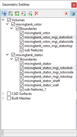
Figure 11.287 - Connecting rotor and stator bottom
|
|
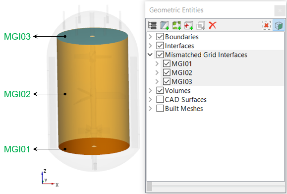
Figure 11.288 - Created interfaces
|
| |
Note: If MGIs are created by connecting the wrong boundaries, delete the created MGIs by clicking on Delete Selected Geometric Entity  icon and then recreate the MGIs. icon and then recreate the MGIs.
|