Contours
There are multiple display variables associated with the particle module. The steps to create contours across the domain are:
- Click Load Results in the Simulation Panel.
- Select the required result file in the ensuing Load Results dialog box, click Open.
Create a section
A section is created with the following steps.
- Click Create a Cross-Section
 in the Geometric Entities Panel. A new section Section 01 is created under Derived Surfaces.
 - Select Section 01 under Derived Surfaces.
- Select Plane Z for Type in the Geometry Tab of Properties Panel.
- Enter 0 for Position.
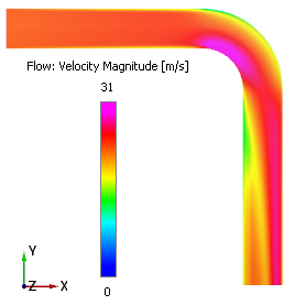
Velocity Magnitude Contours
- Select Section 01 under Derived Variables in the Geometric Entities Panel.
- Select Velocity Magnitude under Derived Variables list for the Variable drop-down list in the Results Panel see, Figure 11.320. For variables and legends, refer Post-Processing.
- Specify Min as 0 m/s and Max as 31 m/s in the Results Panel.
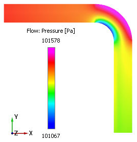
Pressure Contours
- Select Section 01 under Derived Variables in the Geometric Entities Panel.
- Select Pressure under Variables list for the Variable drop-down list in the Results Panel see Figure 11.321.
- Specify Min as 101067 Pa and Max as 101578 Pa in the Results Panel.
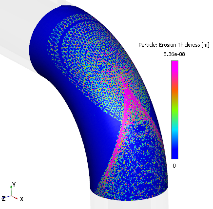
Erosion Thickness Contours
- Select elbow_wall under Boundaries in the Geometric Entities Panel.
- Select Erosion Thickness under Boundary Variables list for the Variable drop-down list in the Results Panel see Figure 11.322.
- Specify Min as 0 m and Max as 5.36e-08 m in the Results Panel.
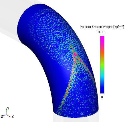
Erosion Weight Contours
- Select elbow_wall under Boundaries in the Geometric Entities Panel.
- Select Erosion Weight under Boundary Variables list for the Variable drop-down list in the Results Panel see Figure 11.323.
- Specify Min as 0 kg/m2 and Max as 0.001 kg/m2 in the Results Panel.