Building the Mesh
This section describes the step-by-step procedure to prepare the mesh for the sand erosion model. The Template Mesher is used to create the mesh for the inlet and outlet and the General Mesher is used to create mesh for the elbow. The settings for the mesh generation are explained in the following steps:
Elbow
- Select General Mesher in the Mesh Panel.
- Select elbow_wall, elbow_outlet and elbow_inlet under CAD Surfaces in the Geometric Entities Panel.
- Click Add Surfaces
 of the CAD Surfaces in the Properties Panel. of the CAD Surfaces in the Properties Panel.
- Enter Maximum Cell Size as 0.02, Minimum Cell Size as 0.0001 and Cell Size on Surfaces as 0.01 .
- To refine the Boundary, select elbow_wall under CAD Surfaces in the Geometric Entities Panel.
- Select User Input for Cell Size on Boundaries and enter 0.0025 for Size in the Properties Panel .
- Click Create Mesh. A new mesh elbow is created under Built Meshes in the Geometric Entities Panel.
- The meshed volume elbow is generated under Volumes.
|
|
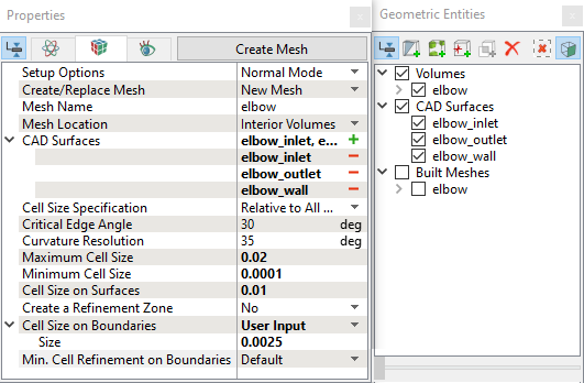
Figure 11.302 - Elbow mesh settings
|
Inlet
-
Select Template Mesh/Surface in the Mesh Panel.
- Enter inlet under Mesh Name in the Properties Panel.
- Select Shape as Cylinder.
- Enter following parameters below to create the exact domain:
- Select User under Setting drop-down list:
No. of Grid in 1st Dir.: 60 No. of Grid in 2nd Dir.: 15 No. of Grid in 3rd Dir.: 60
- Click Build Cylinder Mesh. A new mesh inlet is created under Built Meshes in the Geometric Entities Panel and meshed Volume inlet is generated under Volumes.
- Select Boundaries inlet, dir_max and dir_min under Volumes in the Geometric Entities Panel and rename as inlet_wall, inlet_inlet and inlet_mgi_elbow respectively in the Geometric Entities Panel.
|
|
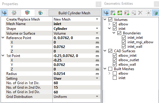
Figure 11.303 - Inlet mesh settings
|
Outlet
-
Select Template Mesh/Surface in the Mesh Panel.
- Enter outlet under Mesh Name in the Properties Panel.
- Select Shape as Cylinder.
- Enter following parameters below to create the exact domain:
- Select User under Setting drop-down list:
No. of Grid in 1st Dir.: 60 No. of Grid in 2nd Dir.: 15 No. of Grid in 3rd Dir.: 60
- Click Build Cylinder Mesh. A new mesh outlet is created under Built Meshes in the Geometric Entities Panel and meshed Volume outlet is generated under Volumes.
- Select Boundaries outlet, dir_max and dir_min under Volumes in the Geometric Entities Panel and rename as outlet_wall, outlet_outlet and outlet_mgi_elbow respectively in the Geometric Entities Panel.
|
|
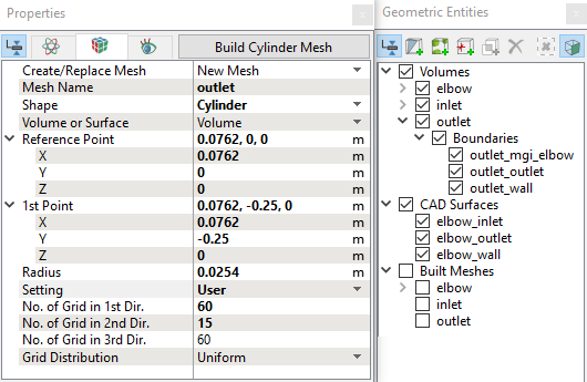
Figure 11.304 - Outlet mesh settings
|
The created mesh is shown below:
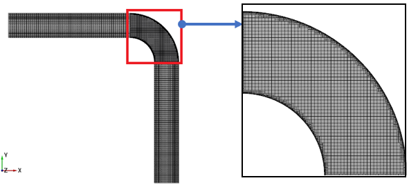
Figure 11.305 - Mesh (cross sectional view)
Create interfaces
In this section, the Mismatched Grid Interfaces (MGIs) are generated between the following boundaries.
The steps to create the MGI is as follows:
- Geometric Entities Panel > Volumes > Boundaries, select entities under Boundaries as shown in Table 11.13.
- Click Connect Selected Boundaries via MGI
 icon to create the MGI entities (Figure 11.306).
A group display of entities can be viewed using the Group Entities by Volumes/Types icon in Geometric Entities Panel toolbar.
| inlet and elbow |
inlet_mgi_elbow and elbow_inlet |
MGI01 |
| elbow and outlet |
elbow_outlet and outlet_mgi_elbow |
MGI02 |
Table 11.13 - Creating interfaces
The new entities are created under MGI in Volumes (see, Figure 11.307).
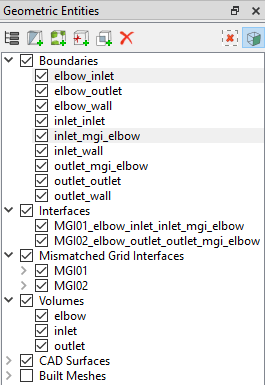
Figure 11.306 - Connecting interfaces of inlet, elbow and outlet
|
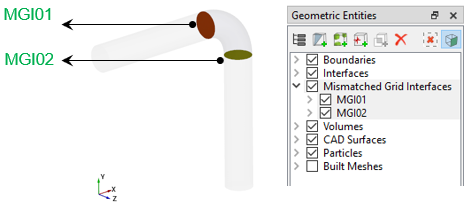
Figure 11.307 - Created mismatched grid interfaces
|