4.2.3 Template Mesh
Simerics-MP/Simerics-MP+ enables generation of volume meshes and/or surfaces for a variety of basic geometrical shapes refer, Figure 4.59. The section explains creation of mesh or surface with the following templates:
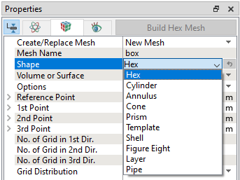
Figure 4.60 - Template shapes |

The above-mentioned shapes are created either as surfaces or volumes. If Volume is selected under Volume or Surface, a meshed volume is created with entities under Volumes and Built Meshes in the Geometric Entities Panel. If Surface is selected under Volume or Surface, only CAD Surfaces are created in the Geometric Entities Panel.
Refer the General Mesher for details on Create/Replace Mesh.
For brief description of each Shape is given below.
Hex Mesh/Surface
 ,
,  and
and  direction respectively.
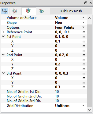
Refer Figure 4.61, for the parameters available in the Hex mesh/surface.
|
Figure 4.62 - Hex volume-points |
Figure 4.63 - Hex volume-mesh |


|
The Size Distribution in 1st Dir., Size Distribution in 2nd Dir. and Size Distribution in 3rd Dir. parameters are available, if the Grid Distribution is selected as Nonuniform. To control the mesh distribution, the following parameters are available under Size Distribution in 1st Dir., Size Distribution in 2nd Dir. and Size Distribution in 3rd Dir as follows:
After these parameters are specified, click Build Hex Mesh to create the hex mesh volume. After these parameters are specified, click Create Surfaces to create the hex CAD Surfaces. |
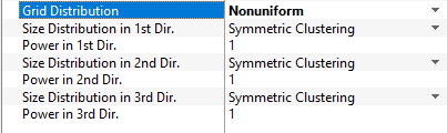
Figure 4.64 - Grid distribution-Nonuniform |


Cylinder Mesh/Surface
|
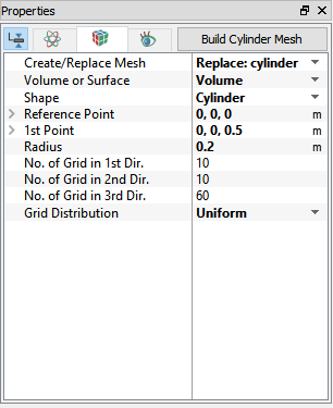
To generate a mesh or surface for a cylinder. The Cylinder mesh/surface operation is accessed as follows: Mesh Panel > Template Mesh/Surface Properties Panel > Geometry Tab > Shape > Cylinder The cylinder is created using following parameters:
Refer Figure 4.69, for the parameters available in the Cylinder mesh/surface.
The Size Distribution in 1st Dir. and The Size Distribution in 2nd Dir. parameters are available, if the Grid Distribution is selected as Nonuniform. To control the Mesh distribution, the following parameters are available under Size Distribution in 1st Dir. and The Size Distribution in 2nd Dir: Symmetric Clustering, Cluster away from Reference Point and Cluster towards from Reference Point. After these parameters are specified, click Build Cylinder Mesh to create the cylinder mesh volume. After these parameters are specified, click Create Surfaces to create the cylinder CAD Surfaces. |


Annulus Volume/Surface
|
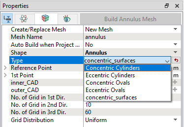
To generate an annular mesh or surface. The Annulus volume/surface operation is accessed as follows: Mesh Panel > Template Mesh/Surface Properties Panel > Geometry Tab > Shape > Annulus Properties Panel > Geometry Tab > Type > [Desired Annulus Type] The annuli are created using the following parameters:
The annuli types available are:
|
Figure 4.70 - Annulus: Type |
To see the Reference Point and parameters of designing the above Cylinders and Ovals: (Refer, Figure 4.71 to Figure 4.73). For concentric surfaces, refer Figure 4.74.
|
|
Figure 4.72 - Concentric ovals-points |
|
|


To see the mesh for the above Cylinders and Ovals: (Refer Figure 4.75 to Figure 4.77). For concentric surfaces mesh, refer Figure 4.78.
|
|
Figure 4.76 - Concentric oval-mesh |
|
|


The Size Distribution in 1st Dir. and The Size Distribution in 2nd Dir. parameters are available, if the Grid Distribution is selected as Nonuniform.
To control the mesh distribution, the following parameters are available under Size Distribution in 1st Dir. and The Size Distribution in 2nd Dir: Symmetric Clustering, Cluster away from Reference Point and Cluster towards from Reference Point.
After these parameters are specified, click Build Annulus Mesh to create the annulus mesh volume.
After these parameters are specified, click Create Surfaces to create the annulus CAD Surfaces.
Cone
|
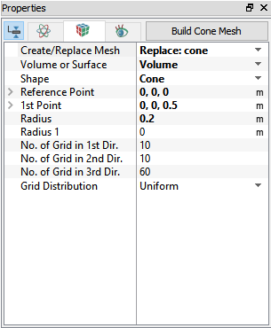
To generate a mesh or surface. The Cone operation is accessed as follows: Mesh Panel > Template Mesh/Surface Properties Panel > Geometry Tab > Shape > Cone The Cone is created using following parameters:
Refer Figure 4.81, for the parameters available in the Cone mesh/surface.
The Size Distribution in 1st Dir. and The Size Distribution in 2nd Dir. parameters are available, if the Grid Distribution is selected as Nonuniform. To control the mesh distribution, the following parameters are available under Size Distribution in 1st Dir. and The Size Distribution in 2nd Dir: Symmetric Clustering, Cluster away from Reference Point and Cluster towards from Reference Point. After these parameters are specified, click Build Cone Mesh to create the cone mesh volume. After these parameters are specified, click Create Surfaces to create the cone CAD Surfaces. |


Prism
|
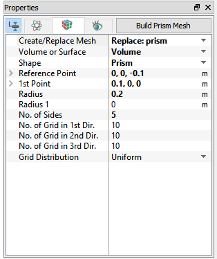
To generate a mesh or surface. The Prism operation is accessed as follows: Mesh Panel > Template Mesh/Surface Properties Panel > Geometry Tab > Shape > Prism The Prism is created using following parameters:
Refer Figure 4.84, for the parameters available in the Prism mesh/surface.
The Size Distribution in 1st Dir. and The Size Distribution in 2nd Dir. parameters are available, if the Grid Distribution is selected as Nonuniform. To control the Mesh distribution, the following parameters are available under Size Distribution in 1st Dir. and The Size Distribution in 2nd Dir: Symmetric Clustering, Cluster away from Reference Point and Cluster towards from Reference Point. After these parameters are specified, click Build Prism Mesh to create the prism mesh volume. After these parameters are specified, click Create Surfaces to create the prism CAD Surfaces. |
 ,
,  and
and  direction respectively.

Plate
|
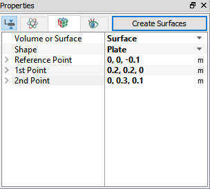
To generate a Surface for a Plate. The Plate operation is accessed as follows: Mesh Panel > Template Mesh/Surface Properties Panel > Geometry Tab > Volume or Surface > Surface Shape > Plate The Plate is created using following parameters:
Refer Figure 4.86, for the parameters available in the Plate mesh/surface.
Figure 4.85 - Plate surface After these parameters are specified, click Create Surfaces to create the plate CAD Surfaces. |

Sphere
|
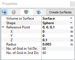
To generate a surface for a sphere. The Sphere operation is accessed as follows: Mesh Panel > Template Mesh/Surface Properties Panel > Geometry Tab > Volume or Surface > Surface Shape > Sphere The sphere is created using the Reference Point and Radius. Refer Figure 4.88, for the parameters available in the Sphere mesh/surface.
Figure 4.87 - Sphere surface After these parameters are specified, click Create Surfaces to create the sphere CAD Surfaces. |

Shell
|
To generate a Volume for a shell. The Shell operation is accessed as follows: Mesh Panel > Template Mesh/Surface Properties Panel > Geometry Tab > Volume or Surface > Volume Shape > Shell The shell is created using the Reference Point Direction, Inner Radius and Outer Radius. Refer Figure 4.90, for the parameters available in the Shell mesh.
Figure 4.89 - Shell Voulme After these parameters are specified, click Build Shell Mesh to create the shell mesh. Shell mesh can also be built using two enclosed surfaces. To do so, change the option of Shape from "Spherical" to "From Surface". User need to pick an "Inner CAD" and "Outer CAD" surfaces from Geometry entities. Structured shell mesh is created and deformed to fit inside the two surfaces. There are some restrictions to the two surfaces.
|

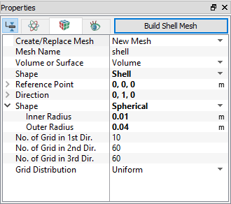
Figure Eight
|
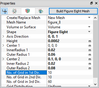
To generate a Volume for a Figure Eight. The Figure Eight operation is accessed as follows: Mesh Panel > Template Mesh/Surface Properties Panel > Geometry Tab > Volume or Surface > Volume Shape > Figure Eight The Figure Eight is created using the Axis Direction, Center, Inner Radius and Outer Radius. Refer Figure 4.92, for the parameters available in the Figure Eight mesh.
Figure 4.91 - Figure Eight Voulme After these parameters are specified, click Build Figure Eight Mesh to create the Figure Eight shape mesh. There are restrictions to the parameters user can use. The two outer circles intersect each other within the region between the two centers. The inner circles must be small enough, so that it is not touching the outer circles intersection line. |

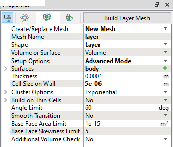
Layer
|
To generate a Volume using Layer. The Layer operation is accessed as follows: Mesh Panel > Template Mesh/Surface Properties Panel > Geometry Tab > Volume or Surface > Volume Shape > Layer The Layer is created using the Thickness, Cell Size on Wall and Cluster Options. Refer Figure 4.95 for the parameters available in the Layer mesh.
|
|