4.1.3 Transform Geometry or Grid
This section explains the set of operations used to modify the geometry of CAD Surface and Volumes.
These options are accessed as follows:
Model Panel > Transform Geometry or Grid.
The related operations are available in the Properties Panel.

Figure 4.8 - Transform Geometry or Grid
OperationThe Operation drop down list contains the following: |
Figure 4.9 - Operation |
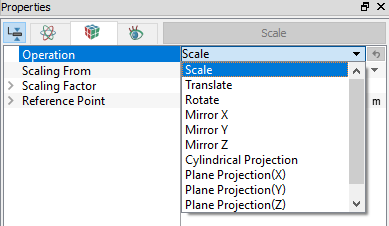
Scale
This is used to change (scale) the dimensions of a CAD Surface or Volume. It is typically used to convert from a given set of units (e.g. inches, millimeters, etc.) into meters which are consistent with the SI units (MKS) used by Simerics-MP/ Simerics-MP+.
- The Scale operator is a multiplier (as opposed to a flag). It is applied (or reapplied) for the selected CAD boundary or volume each time the Scale button in the Mesh Panel is clicked.
- When individual surfaces are scaled, they distort neighboring surfaces by moving any shared vertices.
- Boundaries cannot be scaled.
Following sub parameters need to be specified to scale the geometry or volumes.
- Scaling From: Meter, Millimeter, Inch, Foot, Centimeter, Kilometer and Micron, Decimeter, Nanometer, User defined are in-built options available for scaling.
- Scaling Factor: User defined scaling factor can be given with
 .
. - Reference Point: Point at which scaling has to happen.
Translate
This is used to translate a CAD Surface or Volume. It requires the specification of a Displacement magnitude in the  direction.
- Boundaries cannot be translated.
CAD Surfaces or Volumes can be translated or duplicated using the following:
- Transform Only: Limits the transformation of a CAD Surface or Volume to a simple transformation (i.e. without any duplication).
- Transform & Duplicate: Enables the duplication and transformation of a CAD Surface or Volume.
- New Name: This creates a new name for the duplicate created by the Transformed and Duplicated of a CAD Surface or Volume.
- Same Name: It keeps the original name for the duplicate created by the Transformed and Duplicated of a CAD Surface or Volume.
Normal Displacement: This is used to translate a CAD Surface a specified distance normal to the surface. It requires the specification of a magnitude for Displacement.
|
Note: Boundaries cannot be displaced. |
Rotate
This is used to rotate a CAD Surface or Volume a specified angle about an axis of rotation passing through a point. When selected, this requires setting the  coordinates of the Center and the Direction
  to define the axis of rotation, along with the Angle of rotation in degrees. The direction of rotation uses the right-hand rule such that a positive rotation is counter-clockwise with the direction vector pointing at the observer.
- This does not create a new CAD Surface or Volume, rather rotates the existing entity to a new location.
- When individual surfaces are rotated, they distort neighboring surfaces by moving any shared vertices.
- Boundaries cannot be rotated.
- The rotated surface or volume can be Transformed Only or Transformed and Duplicated.
Cylindrical Projection
This is used to project CAD Surfaces onto a cylinder, see Figure 4.10. It requires the specification of the Center, Direction (axis of symmetry), and Cylinder Radius. The CAD Surfaces, Boundaries and Interfaces can be projected.

|

Figure 4.11 - Cylindrical projection |
|
Note: A common application of the Cylindrical Projection operation is perfecting CAD Surfaces that are supposed to be cylindrical in shape but are not, due to inaccuracies in the CAD .STL file. As shown in Figure 4.10. |
Mirror (X,Y,Z)
Mirror X, Mirror Y or Mirror Z is used to mirror CAD Surfaces or Volumes across a specified plane  ,
,  , and
, and  respectively. This operation does not create a new CAD Surface or Volume, but rather moves it to a new location.
|
Note:Boundaries cannot be mirrored. The mirrored CAD Surface or Volume can be Transformed Only or Transformed and Duplicated. |
Plane Projection (X,Y,Z)
Plane Projection(X), Plane Projection(Y) and Plane Projection(Z) are operations used to project CAD Surfaces onto their respective plane. This requires specification of the Position of the plane. The CAD Surfaces, Boundaries and Interfaces can be projected.

|

Figure 4.13 - Plane projection |
|
Note: A common application of the plane projection operation is to perfect a CAD Surface that is supposed to be planar, but are not due to inaccuracies in the CAD .STL file. As shown in Figure 4.12. |