|
You are here: Additional Templates and Tutorials > PID Controller Template and Tutorial > PID Controller Tutorial > Building the Mesh
|
Building the Mesh
This section describes the step-by-step procedure to prepare the mesh for the mixing pipe of PID controller model. The General Mesher is used to create the mesh.
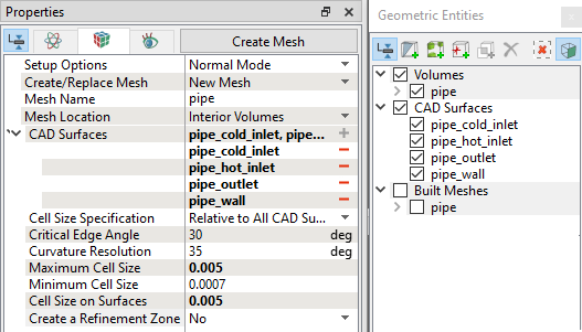
| Note: The mesh can be edited/replaced by selecting it under Built Meshes and modify the mesh parameters in the Properties Panel. Click Create Mesh to reflect the changes. |
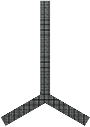
The mesh created for the fluid domain is shown below:
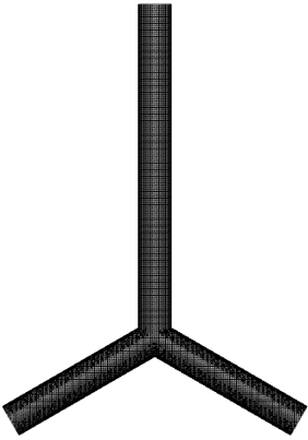 Figure 10.66 - Mesh |