|
You are here: Additional Templates and Tutorials > PID Controller Template and Tutorial > PID Controller Tutorial > Defining Physics and Conditions
|
Defining Physics and Conditions
The physics and conditions are specified as follows:
Adding Modules
|
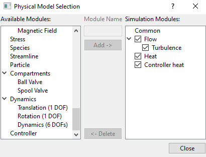
Figure 10.68 - Adding modules |
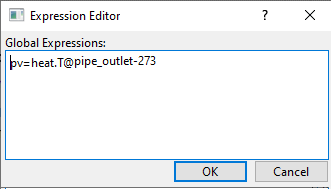
Global Expression
pv=heat.T@pipe_outlet-273 |
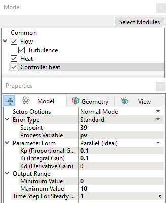
Controller heat Module
|
Boundary Conditions
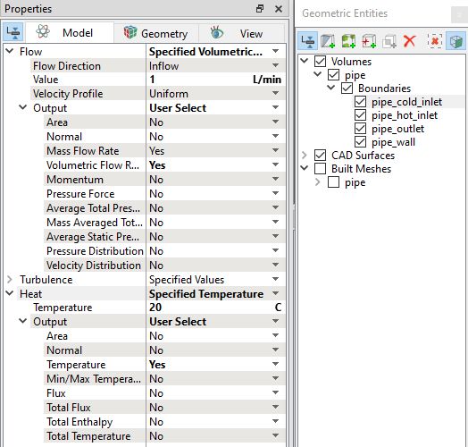
Hot Fluid Inlet
|
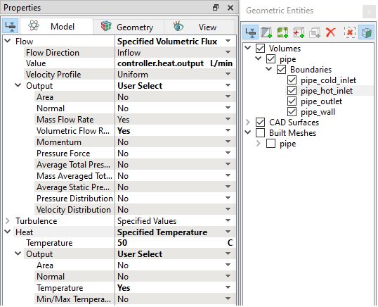
Figure 10.72 - Inlet conditions - Hot fluid |
Outlet
|
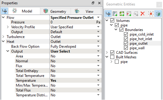
Figure 10.73 - Outlet conditions |
Fluid Properties
|
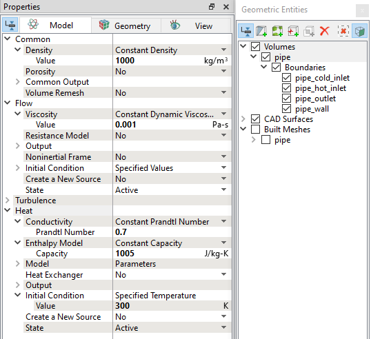
Figure 10.74 - Fluid properties |