12.1 Cross-Sections and Monitoring Points
Sections
|
Sections, also referred as cross-sections are derived planar surfaces that slice through volumes at a user specified location and orientation. They are used to reveal features and/or display a variable.
|
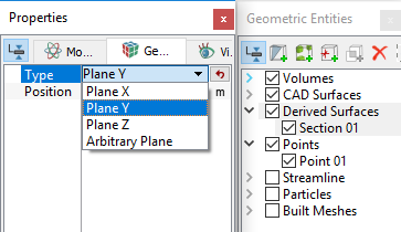
Create a section
|
|
|
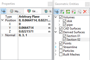
Note: The position of a Section can be moved along its normal direction using the slide bar at the bottom of the Geometric Entities Panel, when the Section is selected. |
|
|
Figure 12.4 - Section (Arbitrary) |


Monitoring Points
A Point is a specified  coordinate within a model, used to record Primary Variables, Property Variables and Derived Variables data at that location.
|
There are three different ways to create Points, distinguished by how their positions changes during a transient simulation. They are:
|
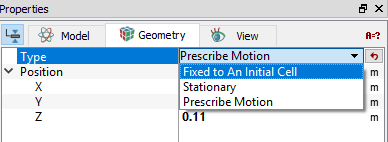
Create a Monitoring Point
|
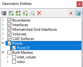
| ´ | Note: The position of Points may be dragged to a new location using the Select |
|
Note: Points may be added during a simulation, but will only record data after being created. For this reasons, monitoring points are typically added prior to running a simulation. |