This tutorial includes:
This tutorial teaches you how to:
Load CAD geometry and specify the topology for complex blade ends.
Enable ATM3D to support meshing with high-fidelity geometry.
Control the display of low-fidelity geometry and high-fidelity geometry.
Control the mesh element distribution near complex blade ends.
Switch which geometry is meshed: high-fidelity (with complex blade ends) or low-fidelity (without complex blade ends).
As you work through this tutorial, you will create a mesh for an inlet guide vane that has partial tip clearance.
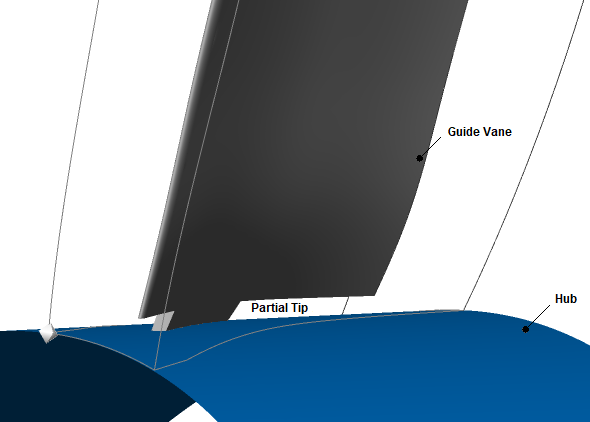
You will model partial tip clearance using the complex blade end feature, which is implemented using high-fidelity geometry.
Meshing with high-fidelity geometry involves a hybrid meshing approach, with blocks of unstructured meshes surrounding high-fidelity geometric features and blocks of structured meshes filling the remainder of the blade passage.
If this is the first tutorial you are working with, it is important to review Introduction to the Ansys TurboGrid Tutorials before beginning.
Create a working directory.
Ansys TurboGrid uses a working directory as the default location for loading and saving files for a particular session or project.
Download the
guide_vane.zipfile here .Unzip
guide_vane.zipto your working directory.Ensure that the following tutorial input files are in your working directory:
InletGuideVane.tginit
InletGuideVane.tin
Set the working directory and start Ansys TurboGrid.
For details, see Setting the Working Directory and Starting Ansys TurboGrid.
Load the geometry:
Click File > Load TurboGrid Init File.
Open
InletGuideVane.tginitfrom the working directory.
Associate CAD objects with complex blade end topology in TurboGrid’s Geometry workspace as follows:
In the Geometry workspace, expand the tree under
Topological Entity Instances>Blade Set>IGVand note that the inlet guide vane,IGV, is defined by a set of topological entities with CAD geometry already assigned.Right-click
IGVand select Insert Complex Blade End.A new topological entity,
ComplexBladeEnd, appears in the tree as a child ofIGV. If you expand the tree belowComplexBladeEndyou will see three child objects:HighFidelityBladeSurfaceHighFidelityHubSurfaceHighFidelityShroudSurface
Using the table below as a guide, assign CAD families, which are listed in the tree within the
CAD Familiesbranch, to the child objects ofComplexBladeEnd.To do this, for each child object of
ComplexBladeEnd, double-click the child object to edit it in the object editor, then click CAD Entity Selector beside the Location setting, then, in the CAD Region Entities dialog box,
select the appropriate CAD family (or select
multiple CAD families using Shift/Ctrl)
and click OK, then, in the object editor, click Apply.
beside the Location setting, then, in the CAD Region Entities dialog box,
select the appropriate CAD family (or select
multiple CAD families using Shift/Ctrl)
and click OK, then, in the object editor, click Apply.Note: An alternative method for assigning CAD families is to, for each child object of
ComplexBladeEnd, in the object selector, select the appropriate CAD family (or select multiple CAD families using Shift/Ctrl) and use the Assign Family To Topology Instance shortcut menu command.Topological Entity
CAD Families
HighFidelityBladeSurface
BLADEHUBTIP, BLADESHROUDTIP, DETAILEDBLADE
HighFidelityHubSurface
DETAILEDHUB
HighFidelityShroudSurface
DETAILEDSHROUD
This completes the geometry definition.
In preparation for generating a mesh that conforms to a high-fidelity geometric feature, in this case complex blade ends, you will enable ATM3D.
In the Mesh workspace, open
Topology Set.Set Mesh Generation Mode to
ATM3D.Click Apply.
Right-click Topology Set and turn off Suspend Object Updates.
After some time, you will see a warning message about the inlet and outlet domains being turned off.
Dismiss the warning message.
The topology and 3D mesh are generated.
There is a pair of toolbar icons for selecting the type of geometry,
high-fidelity or low-fidelity, for which to generate a mesh. Only one icon appears at a time.
If the icon displayed in the toolbar is Use Mesh for Low-Fidelity Geometry
![]() then high-fidelity geometry is selected for meshing, and clicking the icon
would switch to low-fidelity geometry for meshing.
The converse icon is Use Mesh for High-Fidelity Geometry
then high-fidelity geometry is selected for meshing, and clicking the icon
would switch to low-fidelity geometry for meshing.
The converse icon is Use Mesh for High-Fidelity Geometry
![]() .
.
The Display menu contains a pair of commands that correspond to the icons. These commands and icons affect any existing mesh, any mesh subsequently generated, and any mesh subsequently saved.
Ensure that the toolbar icon is Use Mesh for Low-Fidelity Geometry
 so that the meshing of high-fidelity geometry is enabled
(and would be disabled by clicking the icon).
Note that the icon text appears in the lower-left
corner of the user interface.
so that the meshing of high-fidelity geometry is enabled
(and would be disabled by clicking the icon).
Note that the icon text appears in the lower-left
corner of the user interface.
The Mesh workspace holds several objects related to the complex blade ends.
Under
Geometry>Blade Set, expandIGVand note that there is aComplex Blade Endobject.The
IGVobject shows the low-fidelity geometry, which does not feature complex blade ends.The
Complex Blade Endobject shows the high-fidelity geometry, which features complex blade ends.You can toggle the visibility check boxes of these objects independently. Note that the child objects of
Complex Blade Endeach have their own visibility check box.The
Complex Blade Endobject can be edited to adjust the Topology Connection Tolerance settings, which indicate the distance(s) within which separate parts of the geometry should be topologically connected.Expand
Mesh Dataand note theIGV Hub Complex Blade EndandIGV Shroud Complex Blade Endobjects.The visibility check boxes for these objects control the display of lines/surfaces on the geometry that indicate the boundaries of the unstructured meshes near the complex blade ends.
The shortcut menus for these objects contain rendering commands that affect what is displayed; these commands can be used to help visualize problems with the CAD geometry, such as unwanted holes in the surface.
The object editors for these objects contain settings that control the meshing of the complex blade ends.
On the High-Fidelity Geometry tab:
The Enable High-Fidelity Feature check box provides a way to effectively ignore the applicable complex blade end feature when generating a mesh. You might want to do this to save computational time in some cases.
When this check box is selected, the applicable complex blade end can affect the mesh and will affect the mesh provided that the global control (in the Display menu and in the toolbar) for geometric fidelity is set to enable high-fidelity geometry.
When this check box is cleared, the applicable complex blade end is ignored during mesh generation, regardless of the global control setting.
Feature Refinement Factor controls the overall number of mesh elements used in the mesh near the applicable complex blade end.
Growth Rate controls how quickly the element size changes with respect to distance from a nearby wall in the mesh near the applicable complex blade end. This setting affects boundary layer discretization and indirectly affects the number of mesh elements used in the mesh near the applicable complex blade end.
Inflation Layer Mode controls whether the growth rate employed for each wall location is equal to, or allowed to vary from, the specified Growth Rate. The
Constant Expansionoption employs, for each wall location, the specified growth rate. TheLast Aspect Ratiooption employs, for each wall location, a growth rate based on the specified value but modified as needed to achieve a smooth transition in cell aspect ratio where the outermost inflation layer interfaces with the interior mesh.
On the Complex Blade End tab:
Span Location is the normalized span location that approximately bounds the mesh for the complex blade end. The actual boundary is the nearest constant-
Ksurface in the structured mesh, with an integer value of variableK.Elements Per Gap applies to the unstructured mesh near the complex blade end and controls the number of elements used in close proximity to gaps.
Edge Length Refinement Factor controls mesh refinement at feature edges and can vary from 0 to 1, with 0 tending towards a coarse mesh and 1 tending towards a fine mesh.
The Inflation Layer Count Factors settings control, within the unstructured mesh block for the complex blade end, the number of inflation layers off the blade or wall as per the setting name: Blade, Hub, or Shroud.
The Named Selections to Join in Mesh settings create named selections that might be required, depending on the case, to generate the unstructured mesh block for the complex blade end.
The Tip Shell Selection Options settings affect the extent of the tip shell, which is the interface between the structured hex mesh of the passage and the unstructured mesh block for the complex blade end. If necessary, you can extend the tip shell so that it fully encompasses the high-fidelity geometric features of the complex blade end.
The
Mesh Dataobject contains additional settings that affect the unstructured meshes near the complex blade ends. These settings are found on the Hub Complex Blade End and/or Shroud Complex Blade End tabs, which are available when applicable.Expand
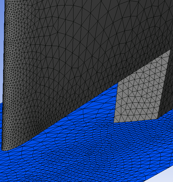
3D Meshand note that there are several mesh objects available for viewing the mesh associated with the complex blade ends.Figure 8.1: Mesh on Blade and Hub Surfaces shows the following
3D Meshobjects near the blade leading edge:IGV_Hub_Complex_Blade_End_bladeandIGV_Hub_Complex_Blade_End_wall. In this figure, the visibilities of other objects have been turned off for an unobstructed view.
Check the 3D mesh statistics:
Open
Mesh Analysis.Some of the mesh statistics have apparent problems based on the current quality criteria. However, if you double-click any of the statistics that indicate a problem, you will see in the 3D Viewer that the indicated elements are related to the unstructured mesh near the blade tips. The quality criteria should ideally be different for the unstructured mesh, which in this case will work without any significant issues in a CFD solver. For example, even in a good unstructured mesh, the minimum face angle will typically fall below 5 degrees in some places.
Close the Mesh Statistics dialog box.
When you save a mesh, the resulting saved mesh reflects either the high-fidelity geometry or the low-fidelity geometry, whichever is currently set.
Save the mesh:
Click File > Save Mesh As.
Ensure that Files of type is set to
Ansys CFX Mesh Files.Set Export Units to
cm.Set File name to
inlet_guide_vane.gtm.Ensure that your working directory is set correctly.
Click Save.