


平面定位器是一个二维区域,仅存在于几何体边界内。要创建新平面,请从主菜单中选择Insert > User Defined > Plane主菜单中的相应选项。
接下来介绍定义平面的可用方法:
YZ 平面
YZ Plane创建垂直于X轴且位于特定X值的平面。输入X的值,使用嵌入式滑块设置,或单击X旁边的框,然后点击Enter Expression
 右侧的X设置,并将其值作为表达式输入。详情请参见Expressions Command.
ZX 平面
ZX Plane创建垂直于Y轴且位于特定Y值的平面。输入Y, set it using the embedded slider, or click in the box beside Y, then click Enter Expression
to the right of the
Y setting and enter its value as an
expression. For details, see Expressions Command.XY 平面
XY Plane的值。Z, set it using the embedded slider, or click in the box beside Z, then click Enter Expression
to the right of the
Z setting and enter its value as an
expression. For details, see Expressions Command.点和法线
Point and Normal创建垂直于Z轴且位于特定Z值的平面。输入
的值。
使用平面上的单个点和垂直于平面的向量创建平面。
要设置点坐标,首先单击其中一个点坐标框。点坐标将以黄色背景显示,查看器将切换到拾取模式。然后您可以直接单击查看器中的可见对象来拾取点。该点可以位于域外。
三点
Three Points您也可以通过在坐标框中输入坐标和/或使用坐标框下方出现的嵌入式滑块来逐一设置坐标。
您也可以通过在坐标框中输入坐标和/或使用坐标框下方出现的嵌入式滑块,逐一设置坐标。
从查看器中拾取法向向量的点时,向量从原点指向拾取的点。
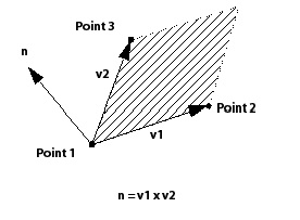
平面的法向向量使用右手定则计算。第一个向量从点1指向点2,第二个向量从点1指向点3,如下图所示。
5.3.3.1.3. 平面边界
None选中时,平面会切割在[T0001]列表中指定的每个域的完整横截面。该平面仅受域边界的限制。Domains list. The plane is only bounded by the limits of the domains.The
Circular选项将平面的边界定义为一个以[T0004]中使用的点为中心的圆。输入圆的半径值,或单击[T0005]旁的框,然后点击[T0006]设置,为圆的半径输入一个表达式。在圆超出[T0007]列表中指定域的区域,平面未定义。Plane Definition. Enter the value of the radius of the circle or click in the box beside Radius, then click Enter Expression to the right of the Radius
setting to enter an expression for the radius of the circle. The
plane is undefined in areas where the circle extends outside of the
domains specified in the Domains list.对于[T0009]选项,平面边界由以[T0010]中选择的点为中心的矩形定义,其在x和y方向上的长度分别为[T0011]和[T0012]。根据[T0013]的不同,您可能需要指定其他方向上的长度。尺寸是相对于平面中心确定的(即平面围绕其中心调整大小)。[T0014]值将平面绕其法线逆时针旋转指定的度数。在矩形超出[T0015]列表中指定域的区域,平面未定义。圆形和矩形选项都有一个[T0016]复选框。如果选中此复选框,则由矩形或圆形定义的区域将用作仅受域边界限制的切片平面上的切除区域。矩形或圆形边界内的区域不构成平面的一部分,但切片平面上这些边界外的所有内容都包含在内。
Rectangularoption, the plane bounds are defined by a rectangle centered about the point selected in the Plane Definition with lengths in the x and y-directions of X Size and Y Size, respectively. You may have to specify lengths in other directions, depending on the Plane Definition. The size is determined with reference to the plane center (that is, the plane is resized around its center). The X Angle value rotates the plane counter-clockwise about its normal by the specified number of degrees. The plane is undefined in areas where the rectangle extends outside of the domains specified in the Domains list.
Both the circular and rectangular options have an Invert Plane Bound check box. If this check box is selected, the area defined by the rectangle or circle is used as a cut-out area from a slice plane that is bounded only by the domain(s). The area inside the bounds of the rectangle or circle does not form part of the plane, but everything on the slice plane outside of these bounds is included.
将[T0019]设置为[T0020]或[T0021]时,平面会向所有方向延伸,直到到达域的边缘。平面上的点对应于平面与网格边缘相交的点。因此,切片平面上的点数与网格间距成反比。Plane Type to either Slice or Sample.
Slice extends the plane in all directions until it reaches the edge of the domain. Points on the plane correspond to points where the plane intersects an edge of the mesh. As a result, the number of points in a slice plane is indirectly proportional to the mesh spacing.
Sample根据所选的平面边界,创建具有圆形或矩形边界的平面。对于[T0023]选项,平面上的点密度对应于[T0024]框架中指定的平面半径,以及Circular option, the density of points on the plane
corresponds to the radius of the plane specified in the Plane
Bounds frame, and the values for the
Radial and Circumferential设置位于Plane Type框架中。对于矩形边界,平面上点的密度对应于平面在每个平面方向上的边界大小,以及Plane Type框架中提供的采样值。采样平面是一组均匀分布的点,与网格间距无关。
拾取模式可用于在查看器中选择和/或平移平面。详情请参见Viewer Toolbar.
参见Color Tab了解详情。
See Render Tab for details.