Content of this section is split into these topics:
Graphical elements can be manipulated not only by the computer mouse per drag and drop but also by using context menus. To this end a right click on the appropriate element is necessary. Doing so the mode of the leading edge can be changed as well as the coordinates of Bezier points for example.
There are some reasonable constraints when working in simplified modes e.g. the inclination angle of the trailing edge can only be set when hub and shroud are in Bezier mode both.
Display Options
In the Display Options panel some graphical representations can be activated for illustration:
|
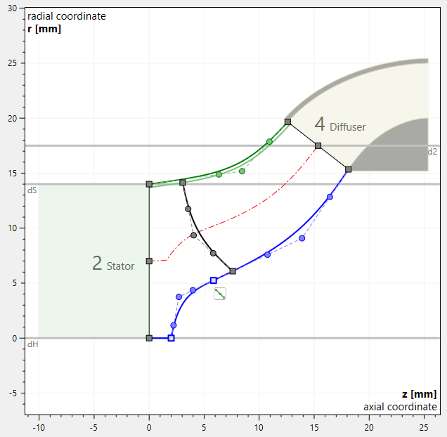
Adjacent components on inlet and outlet side are displayed for information.
|
|
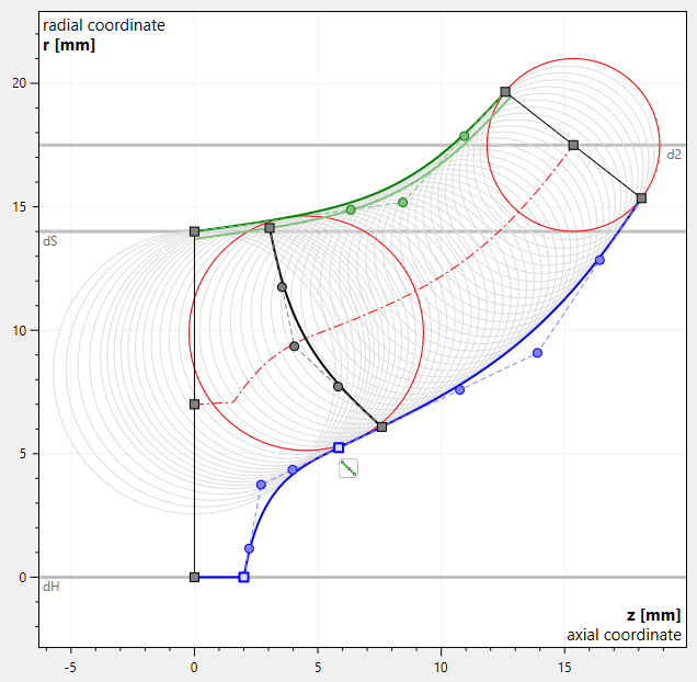
Area circles used for calculation of cross section area. |
|
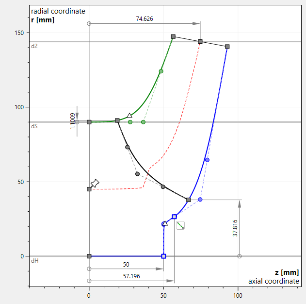
Dimensioning of the most important control points is displayed permanently. If the option is not activated, only the dimension of the control point near the mouse cursor is displayed. |
|
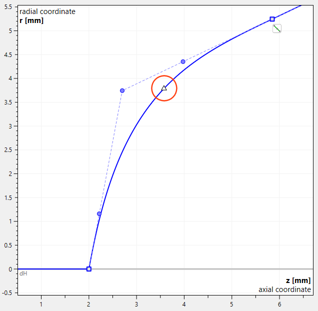
Curvature maximum Δ point is displayed on hub and shroud curves. |