► IMPELLER | Meridional contour ![]()
The design of the meridional contour is the second important step to design the impeller.
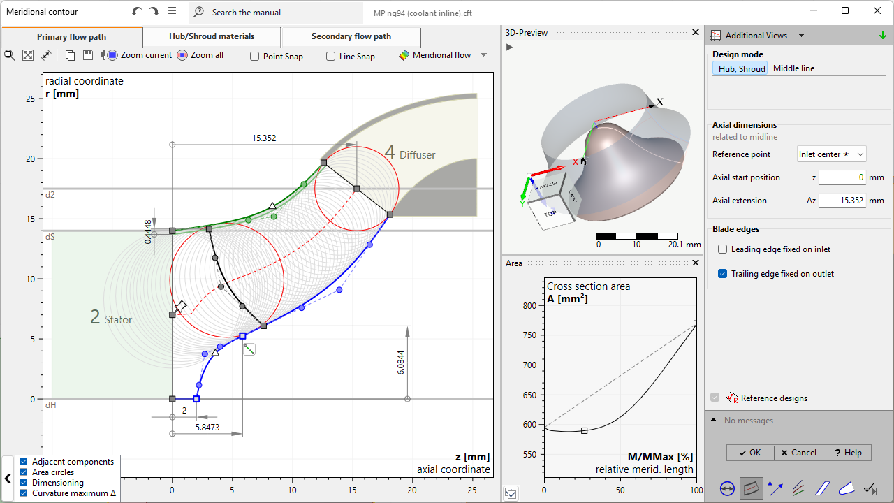
Meridional design is divided in 3 parts:
•Primary flow path
This contains the design of the primary flow path. Necessary for the following design steps.
•Hub/Shroud materials (optionally)
This contains the design of hub and/or shroud material solids. This is an optional part focusing on stress analysis.
•Secondary flow path (optionally)
This contains the design the secondary flow path behind hub and/or shroud. This is an optional part focusing on detailed flow analysis.
Possible warnings
Problem |
Possible solution |
|---|---|
Hub/ Shroud contour has discontinuities inside blade region. |
|
The hub resp. shroud contour is divided into sub-curves who are not connected smoothly in blade region. |
Adjust hub resp. shroud contour and apply smoothness at connectors who are inside blade region. |
Angle between hub/ shroud contour and inlet/ outlet is not recommended. |
|
The current angle between hub/shroud contour and inlet/outlet can cause problems in Model finishing. |
Manipulate hub/shroud contour or move inlet/outlet to change the current angle to inlet/outlet.
Contour may contain extremely small and unnecessary parts which should be removed. |
Hub/ shroud contour of primary flow path contains artifacts. |
|
The Hub/ shroud contour contains very small segments which are classified as artifacts and can cause problems in geometric processing. |
Artifacts should be removed to increase stability and quality of geometric processing. |
Current "Edge extent (shroud > hub)" setting of "Leading/ Trailing edge main/ splitter blade" is not recommended at current meridional edge position. |
|
Selected edge extent specification "Δz = const." or "Δr = const." is difficult to fulfill for the current meridional shape. |
Select another option in the context menu of the edge for "Edge extent (shroud > hub)". In general, "independent" is the most robust option and should never generate this warning. |
Primary flow path is invalid! Failed to satisfy all geometric constraints. |
|
The system of user defined constraints for the primary flow path cannot be solved, which results in an invalid meridional geometry. |
Typically, the critical parts of the geometry are marked in red color. These parts should be adapted. Alternatively one can return to the previous state using the undo feature. |
Hub contour intermittently touching z-axis (r=0) is not supported. |
|
The hub curve is touching the z-axis internally. Before and behind it the radius is greater than 0 creating a complete constriction. |
Avoid hub regions at r = 0 internally |
Meridional contour has an invalid topology. (inside out) |
|
The sense of circulation of the closed wire containing the inlet, shroud, outlet and hub curve in this specific order is counter-clockwise. |
Manipulate meridional curves to guarantee a clockwise sense of circulation or adjust inlet and outlet in main dimensions. |
Contour has invalid edges. (Material solids & Secondary flow path) |
|
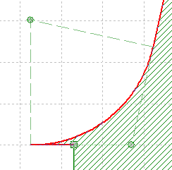
When using Line/Arc Segment curves with rounded corners the defined radius could be too large. This can result in sharp edges and very small segments.
|
Corner radius of the invalid (red) curve has to be reduced. This could be achieved by dragging the circle center. The curve is valid when it is no longer drawn in red. |