|
You are here: Automotive Templates and Tutorials > Automotive Tutorials > Dual Heat Exchanger Tutorial > Defining physics and conditions
|
Defining physics and conditions
The physics and conditions are specified as follows.
Adding modules
|
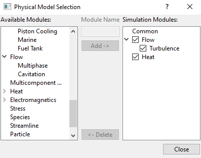
Figure 7.316 - Adding modules |
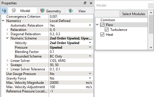
Flow parameters
|
Figure 7.317 - Flow operating parameters |
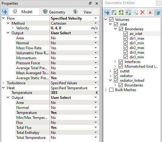
Air outlet
|
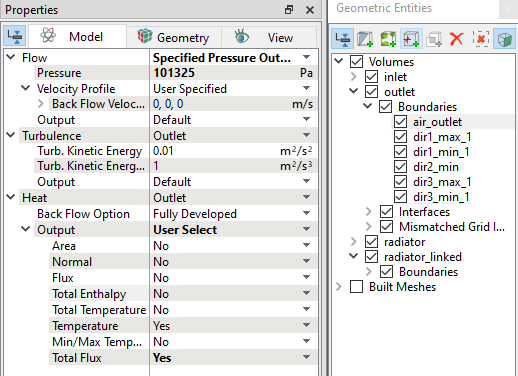
Figure 7.319 - Air outlet conditions |
Coolant inlet
|
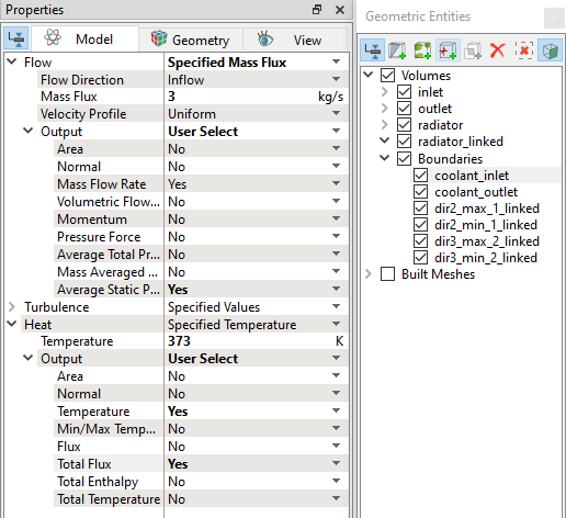
Figure 7.320 - Coolant inlet conditions |
Coolant outlet
|
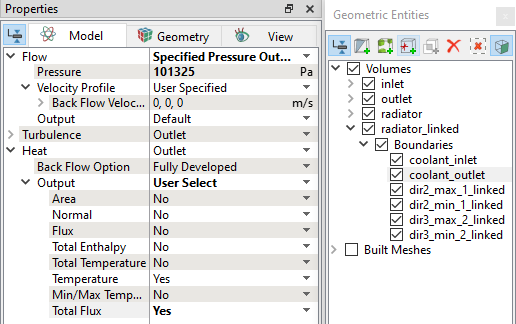
Figure 7.321 - Coolant outlet conditions |
Air properties
|
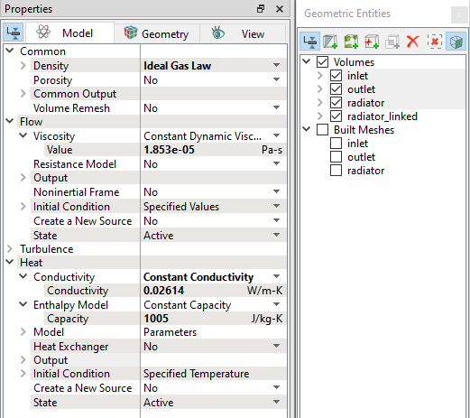
Figure 7.322 - Air properties |
Coolant properties
|
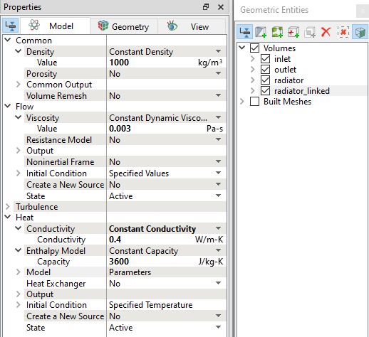
Figure 7.323 - Coolant properties |
Two fluid heat exchanger model - Air
|
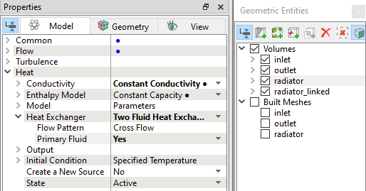
Figure 7.324 - Two fluid heat exchanger - Air properties |
Two fluid heat exchanger model - Coolant
qm = heat.Qm qs = heat.Qs rad_ntu = table("rad_ntu.txt",qs,qm) |
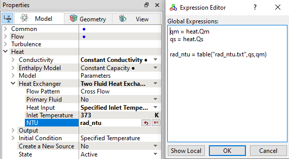
| ´ | Note: The NTU is obtained from the heat rejection data of the heat exchanger, which is a function of primary and secondary fluid flow rates. An executable is available to convert the heat rejection data into NTU data. |
Resistance model
|
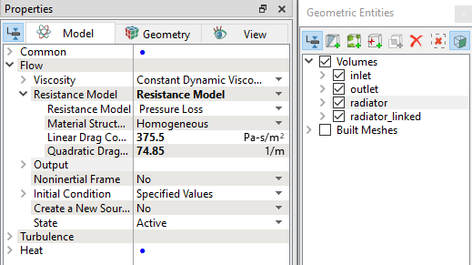
Figure 7.326 - Resistance model |
| Note: The two Coefficients under Resistance Model are obtained from Q-DP Curve for air-side of the radiator. Refer to Porous Media Resistance Model for more details. |