Defining Physics and Conditions
The physics and conditions are specified as follows:
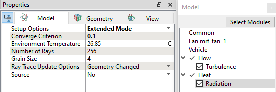
Modules
|
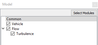
Figure 17.1 - Adding Modules |
Operating Parameters
Fan
|
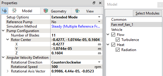
Figure 17.2 - Fan module parameters |
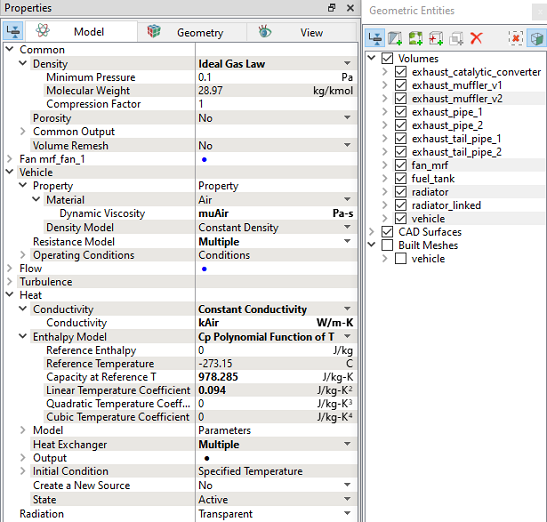
Vehicle
|
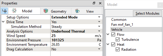
Figure 17.3 - Vehicle module parameters |
Heat Module
|
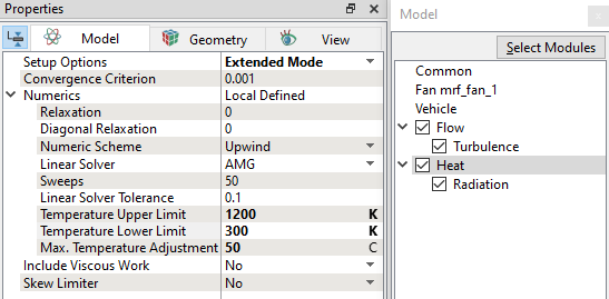
Figure 17.4 - Heat module parameters
|
|
Radiation
|
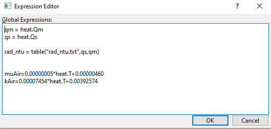
Global Expression
qm = heat.Qm qs = heat.Qs
rad_ntu = table("rad_ntu.txt",qs,qm)
muAir=0.00000005*heat.T+0.00000460 kAir=0.00007454*heat.T+0.00392574
|
Radiator (air) properties
|
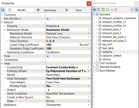
Figure 17.8 - Radiator (air) properties |
| ´ | Note: For calculation of Linear Drag Coefficient and Quadratic Drag Coefficient, refer Template. |
Radiator (Coolant) properties
Enter the following under Heat Exchanger drop-down list of Heat module.
|
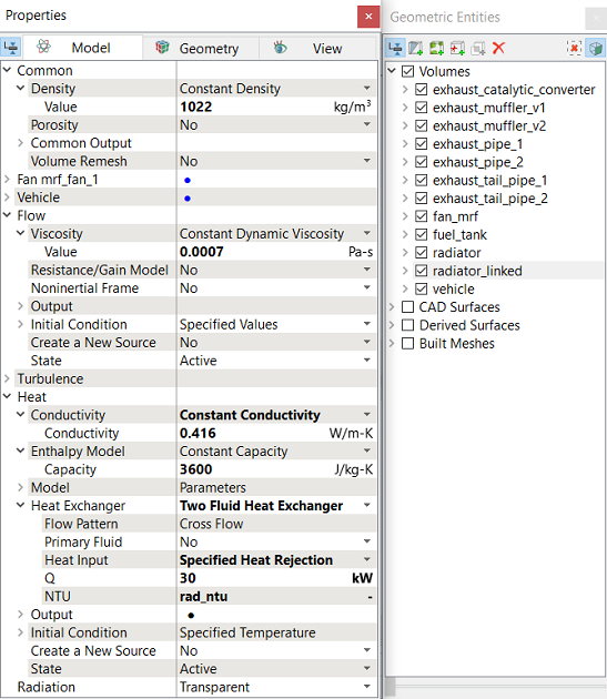
Figure 17.9 - Radiator (Coolant) properties |
Solid Properties
|
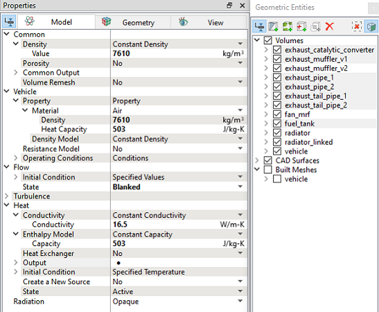
Figure 17.10 - Solid properties - Exhaust |
| Volumes | Density (kg/m3) | Conductivity (W/m-K) | Capacity (J/kg-K) |
|---|---|---|---|
|
exhaust_catalytic_converter, exhaust_muffler_v1, exhaust_pipe_1, exhaust_pipe_2, exhaust_tail_pipe_1, exhaust_tail_pipe_2 |
7610 | 16.5 | 503 |
| fuel_tank | 1600 | 0.25 | 1200 |
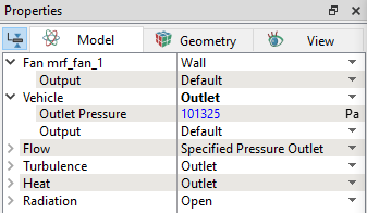
Boundary conditions
Some boundary conditions for the simulation are automatically set by the Vehicle template:
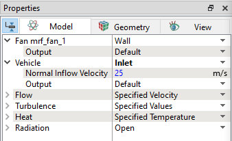
Figure 17.11 - Vehicle Inlet |
Remaining boundary conditions are specified as follows:
Vehicle Boundaries
-
Select engine from the Boundaries list under Volumes in the Geometric Entities Panel.
-
Select Specified Temperature from the Heat drop-down list and enter 95 C for Temperature in the Model Tab in the Properties Panel.
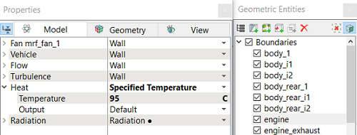
Figure 17.13 - Engine Surface Temperature
- Select engine_exhaust from the Boundaries list under Volumes in the Geometric Entities Panel.
- Select Specified Temperature from the Heat drop-down list and enter 600 C for Temperature in the Model Tab in the Properties Panel.
- Select engine_transmission from the Boundaries list under Volumes in the Geometric Entities Panel.
- Select Specified Temperature from the Heat drop-down list and enter 50 C for Temperature in the Model Tab in the Properties Panel.
- Select all Boundaries, except vehicle_floor, vehicle_inlet, vehicle_outlet, vehicle_roof, vehicle_side1 and vehicle_side2 from the Boundaries list under Vehicle Volumes in the Geometric Entities Panel.
- Enter 0.9 for Emissivity under the Options drop-down list.
- Select Interfaces exhaust_catalytic_converter, exhaust_muffler, exhaust_pipe_1, exhaust_pipe_2, exhaust_tail_pipe_1 and exhaust_tail_pipe_2 from the Interfaces list under Vehicle Volumes in the Geometric Entities Panel.
- Enter 0.7 for Emissivity under the Options drop-down list.
- Select Interfaces fuel_tank from the Interfaces list under Vehicle Volumes in the Geometric Entities Panel.
- Enter 0.9 for Emissivity under the Options drop-down list.
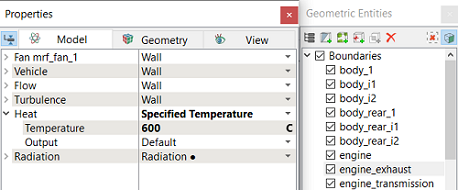
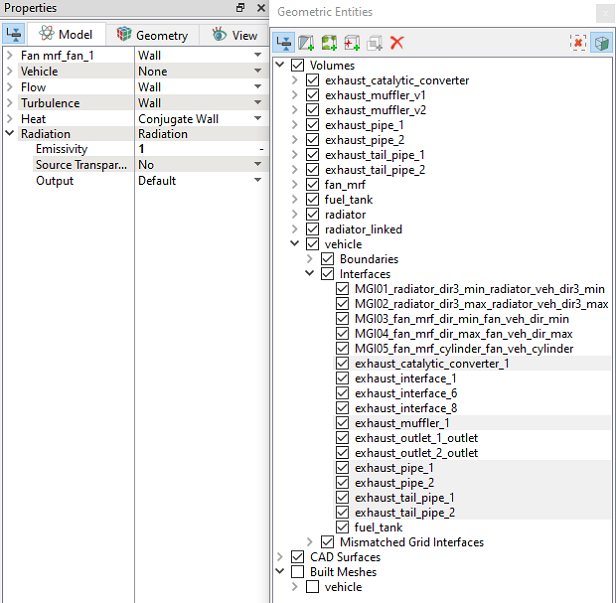
Figure 17.15 - Example for assigning Emissivity
Exhaust Inlet
- Select exhaust_inlet from the Interface list under Volumes in the Geometric Entities Panel.
- Select Specified Interface option under Operation list in Split/Combine Geometry or Grid in the Mesh Panel. Click Seperate Interface. It generates two boundaries (exhaust_inlet_i1 and exhaust_inlet_i2) under exhaust_muffler_v2 and vehicle Volumes separately.
- Select exhaust_inlet_i1 from the Boundaries list under Volumes in the Geometric Entities Panel.
- Select Specified Mass Flux from the Flow drop-down list and enter 0.04 kg/s for Mass Flux in the Model Tab in the Properties Panel.
-
Select Specified Temperature from the Heat drop-down list and enter 700 C for Temperature in the Model Tab in the Properties Panel.
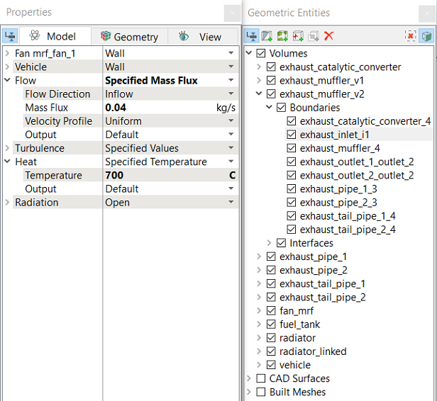
Figure 17.16 - Exhaust Inlet Boundary condition
Radiator (Coolant) Boundaries
- Select radiator_dir1_min_linked from the Boundaries list under Volumes in the Geometric Entities Panel.
- Select Specified Volumetric Flux option from the Flow drop-down list and enter 60 L/min for Volumetric Flux in the Model Tab in the Properties Panel.
-
Select Yes for Temperature, Total Flux under the Output for Heat drop-down list.
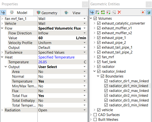
Figure 17.17 - Coolant Inlet Boundary condition
- Select radiator_dir1_max_linked from the Boundaries list under Volumes in the Geometric Entities Panel.
- Select Specified Pressure Outlet from the Flow drop-down list and enter 101325 Pa for Pressure in the Model Tab in the Properties Panel.
-
Select Yes for Temperature, Total Flux under the Output for Heat drop-down list.
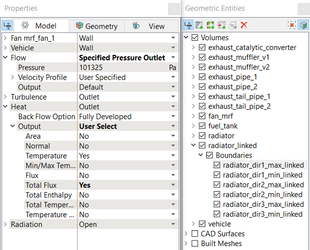
Figure 17.18 - Coolant Outlet Boundary condition
| ´ |
Note:
|