|
You are here: Automotive Templates and Tutorials > Vehicle Template > Full Vehicle Modelling > Wind Tunnel
|
Wind Tunnel
This places a bounding box around a vehicle body to be meshed. It is used as the starting point for subsequent cell division.
There are three ways to add the wind tunnel in Simerics-MP+, described as follows:
- Provide Surfaces
- Provide Margins: The specification of maximum and minimum sides of the wind tunnel with respect to the vehicle can be calculated as follows:
- Provide Vector & Point
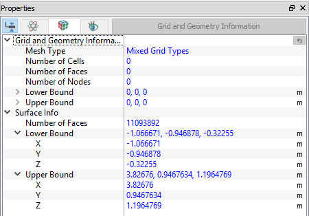
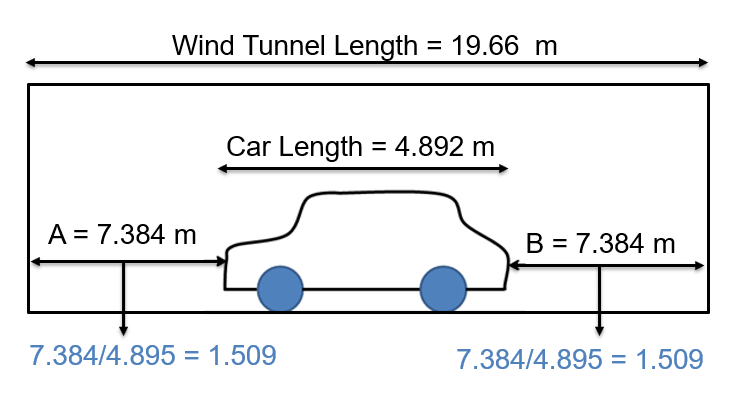
In this case, the vehicle is placed in the center of the wind tunnel, the front and back length is 1.509 times the car length in "x" direction. The vehicle dimensions can be calculated from the grid and geometric information. By subtracting the lower bound from the upper bound of the surface info, all three dimensions of the car can be obtained. The car dimensions are as shown in Figure 7.8
L = 4.892 m, W = 1.894 m, H = 1.652 m.
Wind tunnel "x" length (l): 19.66 m.
Car Length in "x" direction (L): 4.892 m.
Distance from front of car to inlet of wind tunnel (f) = (19.66 – 4.892)/2 = 7.384 m.
Distance from rear end of car to outlet of wind tunnel (r) = (19.66 – 4.892)/2 = 7.384 m.
So, for the relative dimensions, calculating the xmin and xmax ratios by dividing (f)/(L) and (r)/(L) respectively, as shown in the Figure 7.9.
This procedure needs to be repeated to calculate the relative min and max sizes in for "y" and "z" directions.
Wind tunnel "y" length = 14.02 m.
Wind tunnel "z" length = 8.23 m.
|
|