Component Meshing
The vehicle meshing is performed by providing necessary geometry information (such as surfaces) and related parameters. It mainly includes parameters pertaining to Tunnel surfaces, Vehicle surfaces, Grill surfaces, Heat exchangers and Fan.
Tunnel
Any wind tunnel used for the vehicle simulation is modelled using Tunnel Definition. The tunnel defined using Vehicle template should be of rectangular shape.
|
Tunnel Definition can be specified using three available options:
|
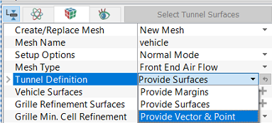
Figure 7.15 - Tunnel definition |
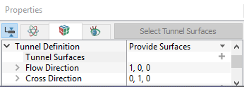
- Provide Surfaces: In this method, the outer surfaces of the wind tunnel can be directly provided. This option is typically used when tunnel surfaces are already created using other CAD packages and imported into Simerics-MP+.
- Tunnel Surfaces: The surfaces of the wind tunnel are selected under CAD Surfaces in the Geometric Entities Panel and click Add Surfaces
 icon for Tunnel Surfaces.
 - Flow Direction: This is the direction of the wind in the tunnel. Typically, this should be aligned with the tunnel inlet. The direction is specified with the coefficients of flow direction unit vector in
 coordinates.
 - Cross Direction: Cross direction is explained using the vector right hand rule as shown in the Figure 7.16. The direction is specified with the coefficients of cross direction unit vector in
 coordinates.
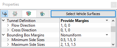
 - Provide Margins: In this method, margins are specified by a fraction of vehicle dimension in that direction. The
 and
and  directions correspond to the flow and cross directions and
  direction is determined by right hand vector rule.
- Bounding Box Margin: Two types of margins are available under this option which are Nonuniform and Diagonal Positions.
Nonuniform: This defines a bounding box that has different dimensions in
 ,
,  and
and  directions. The values of the Minimum Side Sizes and Maximum Side Sizes are calculated based on the ratio of, the distance the car is in each direction from the walls of the wind tunnel, to the car size in that direction. So the values are all relative to the length, width and height of the car. The calculation procedure is explained in virtual wind tunnel.
Diagonal Positions: This defines a bounding box that has different dimensions in
 ,
,  and
and  directions. The values of the Minimum Corner Position and Maximum Corner Position are provided to calculate the wind tunnel dimension.
-
Provide Vector and Point: In this method, tunnel surfaces are created by specifying the following parameters:
- Flow Direction.
- Cross Direction.
- Floor Point: This is the coordinate of one point through which the floor of the wind tunnel passes.
- Reference Front Tire Surfaces: Select the front tire surfaces under CAD Surfaces in the Geometric Entities Panel and click Add Surfaces icon.
- Front Tire Center: Specify the center of the front tire in
 co-ordinates. This is auto-populated with default value once the surface is selected.
 - Reference Rear Tire Surfaces: Select the rear tire surfaces under CAD Surfaces in the Geometric Entities Panel and click Add Surfaces icon.
- Rear Tire Center: Specify the center of the rear tire in
 co-ordinates. This is auto-populated with the default value once the surface is selected.
 - View Tunnel details: This displays the dimensions of the wind tunnel upon the selection of Yes. Details of the wind tunnel are Length, Width, Height and Wheelbase Center To Front.
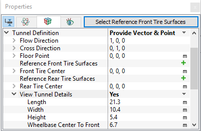
Figure 7.19 - Provide vector and Point
|
|
Figure 7.17 - Provide surfaces |

|
|
Figure 7.18 - Provide margins |
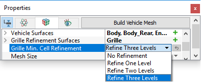
Vehicle
|
Figure 7.20 - Grill min cell refinement |
Fans
|
Fans can be added by selecting one of the following in the Add Fan drop-down list.
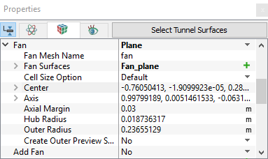
Fan Mesh Name: Provide the name. |
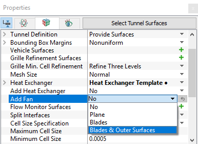
Figure 7.22 - Fan definition |
- Plane: This option is used to define the fan using fan curves.
- Blades: If the fan geometry is available, use this option to model the fan using MRF approach.
- Fan Surfaces: Select blade surfaces under CAD Surfaces in the Geometric Entities Panel and click Add Surfaces icon.
- Fan blade center and axis are user input. The Outer Radius is automatically calculated based on the center and axis provided.
- The axial and radial margins are used to create the outer casing of the MRF zone. Preview surfaces can be created to check MRF casing.
- Cell Size Option.
-
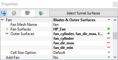
Blades and Outer Surface: This feature is used when the fan blade geometry and casing are available.
- Fan Surfaces: Select blade surfaces under CAD Surfaces in the Geometric Entities Panel and click Add Surfaces icon.
- Outer Surfaces: Select outer casing surfaces under CAD Surfaces in the Geometric Entities Panel and click Add Surfaces icon.
- Cell Size Option.

Figure 7.25 - Components mesh on Y plane section
- Fan Surfaces: Select blade surfaces under CAD Surfaces in the Geometric Entities Panel and click Add Surfaces
|
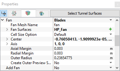
Figure 7.24 - Fan blades |

Flow Monitor Surfaces
Specify the surfaces on which the flow rate is to be monitored, as shown in Figure 7.11.
Internal Volume Definition
This feature is available for Underhood Thermal meshing mode. Specific components that need to be retained for temperature prediction and internal volume analysis can be added by selecting one of the following in the drop-down list.
- Volume Surfaces: This option allows adding all the surfaces that define a component, which need to be retained.
New Volume Surfaces: Select all the surfaces of components under CAD Surfaces in the Geometric Entities Panel.
- Identifying Boundaries: This option allows adding only one surface that defines a component which need to be retained.
Boundaries: Select all the boundaries that correspond to specific components under CAD Surfaces in the Geometric Entities Panel.
Internal Volume Options
This feature controls the number of volumes that need to be retained by selecting one of the following.
- Biggest Identified Volumes: This option allows to retain all the biggest volumes that are connected to selected surfaces. Smaller volumes that get split due to meshing will not be retained.
- All Identified Volumes: This option allows to retain all the volumes that are connected to selected surfaces.
- All Volumes: This option allows to retain all the neighboring volumes apart from the volumes that are connected to the selected surfaces.
Fan Solid Volumes
Fan solid volume can be retained by selecting Yes or No from the drop-down list.
Split Interface
Interfaces are separated automatically, if Split Interface (see, Figure 7.12) is set as Yes.