Computational Domain
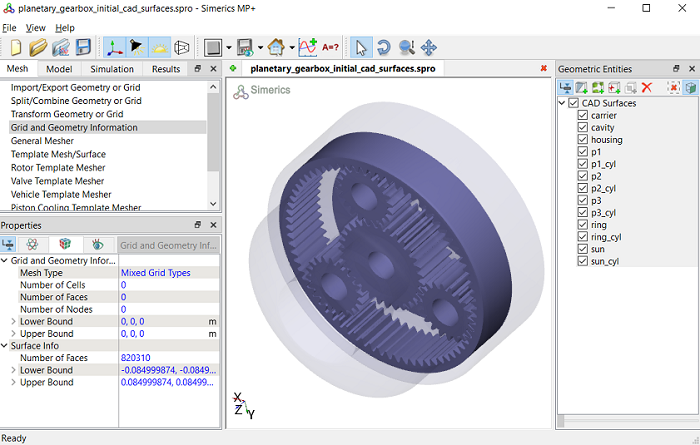
This section explains the preparation of surfaces to create the computational domain. This is done with the operations splitting, combining and renaming of the surfaces.
Figure 7.175 - Planetary gearbox CAD surfaces
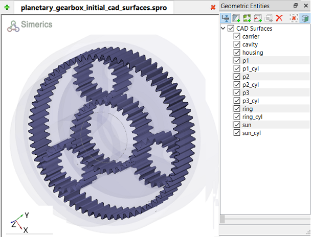
Gear Surfaces
- Select the CAD Surfaces p1 in the Geometric Entities Panel.
- Enter Angle = 75 deg and method a Split by Mouse. Select from the drop-down list in the Properties Panel.
-
Click on the surfaces highlighted in brown, as shown in Figure 7.177. Four new CAD Surfaces are created in the Geometric Entities Panel.
-
Delete all p1 gear surfaces and retain only gear external surface, as shown in Figure 7.178 and rename surface according to gear, here it is p1. The template mesher requires only gear teeth profile for meshing.
-
Similarly, split and rename p2, p3, sun and ring CAD Surfaces as explained in above steps 1 to 4 and retain only gear teeth surfaces as shown in Figure 7.179.
|
|
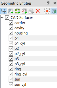
Figure 7.176 - Gear surfaces
|
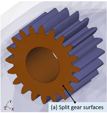
Figure 7.177 - Split planar surfaces
|
|

Figure 7.178 - Seperated gear surface
|
Figure 7.179 - Gear surfaces
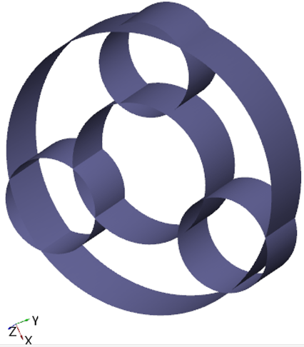
Gear Outer Surfaces
- Select CAD Surfaces p1_cyl in the Geometric Entities Panel.
- Select Split by Angle from the Operation drop-down list in the Properties Panel.
- Enter 75 deg for Angle and method as Split by Mouse.
-
Click on the surfaces highlighted in brown, as shown in Figure 7.181. Three new CAD Surfaces are created in the Geometric Entities Panel.
-
Delete all p1_cyl gear surfaces and retain only cylinder outer surface, as shown in Figure 7.182 and rename surface according to gear cylinder, here it is p1_cyl. The template mesher requires only cylinder outer profile.
- Similarly, split and rename CAD Surfaces p2_cyl, p3_cyl, sun_cyl and ring_cyl as explained in above steps 1 to 4 and retain only cylinder outer surfaces, as shown in Figure 7.183.
|
|
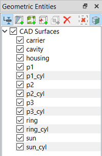
Figure 7.180 - Gear outer surfaces
|
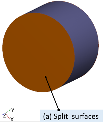
Figure 7.181 - Split gear outer surfaces
|
|
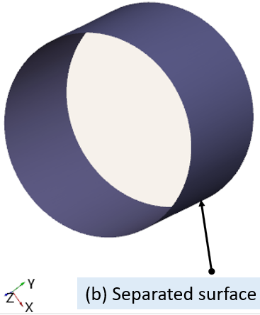
Figure 7.182 - Split gear outer surfaces
|
Figure 7.183 - Cylinder outer surfaces
Carrier Surfaces
- Select CAD Surfaces carrier in the Geometric Entities Panel.
- Select Split by Angle from the Operation drop-down list in the Properties Panel.
- Enter Angle = 75 deg and method as Split All. Four new CAD Surfaces are created.
- Rename the CAD Surfaces carrier_01, carrier_02, carrier_03 and carrier_04 as carrier_mgi_housing_top, carrier_mgi_housing_bot, carrier_mgi_housing_radial and carrier respectively in the Geometric Entities Panel.
|
|
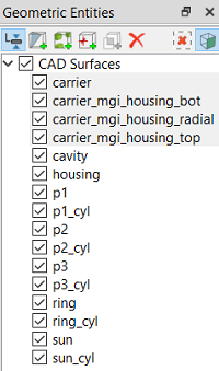
Figure 7.184 - Carrier surfaces
|
Cavity Surfaces
- Select CAD Surfaces cavity in the Geometric Entities Panel.
- Select Split by Angle from the Operation drop-down list in the Properties Panel.
- Enter Angle = 75 deg and method a Split by Mouse.
-
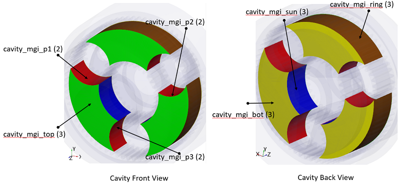
Click on the surfaces highlighted in different colours, as shown in Figure 7.186.
-
Combine three axial surfaces as highlighted in green colour and rename as cavity_mgi_top, as shown in Figure 7.186.
- Similarly, combine two radial surfaces of each gear as highlighted in red colour and rename with respect to each planet gear surfaces as cavity_mgi_p1, cavity_mgi_p2 and cavity_mgi_p3.
-
Combine three radial surfaces of sun gear, as highlighted in blue and rename as cavity_mgi_sun.
-
Combine three radial surfaces of ring gear, as highlighted in brown and rename as cavity_mgi_ring.
-
Combine three axial surfaces, as highlighted in yellow and rename as cavity_mgi_bot.
|
|
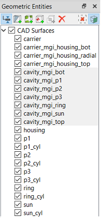
Figure 7.185 - Cavity surfaces
|
Figure 7.186 - Split/combine and rename cavity surfaces
Housing Surfaces
- Select CAD Surfaces housing in the Geometric Entities Panel.
- Select Split by Angle from the Operation drop-down list in the Properties Panel.
- Enter Angle = 75 deg and method as Split by Mouse.
-
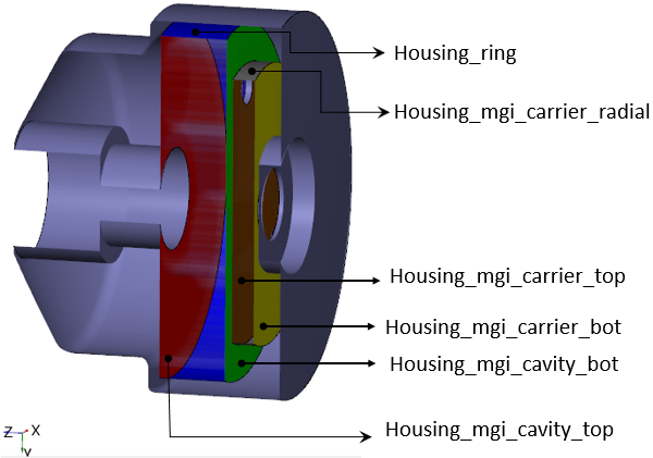
Click on the surfaces highlighted in different colours as shown in Figure 7.188. To perform splitting operation, create section (X= -0.021) and Select Option as Keep Positive Side in View Tab of Properties Panel. Upon selection of housing CAD Surfaces, one can view surfaces to split.
- Rename the CAD Surfaces highlighted in blue as housing_ring, grey surface as housing_mgi_carrier_radial, brown surface as housing_mgi_carrier_top, yellow surface as housing_mgi_carrier_bot, green surface as housing_mgi_cavity_bot and red surface as housing_mgi_cavity_top respectively in the Geometric Entities Panel.
-
Combine the remaining housing surfaces and rename as housing.
|
|
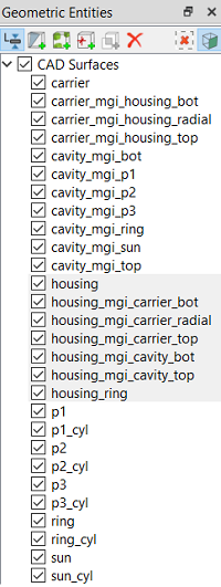
Figure 7.187 - Housing surfaces
|
Figure 7.188 - Split/combine and rename housing surfaces