6.14.1 Geometry and Domain
The simulation of the scroll compressor requires the understanding of the geometry and the fluid domain enclosed by the surfaces of the compressor. The general fluid volume of the scroll compressor and prerequisite steps, before taking into Simerics-MP+, are described here.
Prerequisite steps
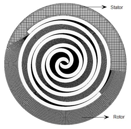
- The fluid domain of the scroll rotor needs to be cut to form separate moving (rotor) and stationary (stator) regions. The moving region contains the whole rotor (orbiting scroll) and the stator (stationary scroll) around it. The moving region is meshed by the Rotor Template Mesher while the stationary region is meshed by general mesher.
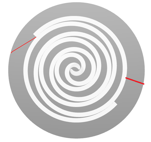
- The cuts are required to form a relatively smooth outline for the stator. Generally, on the stator surface, the cut should form a small angle to the rest of the outline as shown in Figure 6.782 and Figure 6.783. The cut at the stator end is made almost perpendicular to the stator outlines.
Fluid Domain
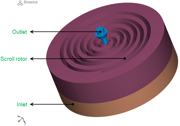
Figure 6.784 - Scroll compressor- Fluid domain
The fluid volume in a scroll compressor is defined by CAD Surfaces which enclose them. The scroll model primarily consists of the following volumes: Inlet, Scroll rotor, Outlet.
Inlet: The fluid enters the compressor through the Inlet boundary. Pressure and temperature is generally specified as a boundary condition at the inlet, while the other surfaces of the inlet volume are treated as walls.
Scroll rotor: The fluid volume enclosed between the stationary and orbiting involutes. The fluid gets trapped and compressed in this volume.
Outlet: The fluid exits the compressor at the outlet boundary. Pressure is generally specified as a boundary condition at the outlet, while the other surfaces of the outlet volume are treated as walls.