|
You are here: Marine Templates and Tutorials > Marine Hull Template > Modelling Marine Vessel > Propeller Models
|
Propulsion Source
The objective in specifying a propulsion source is to quantify the force causing the propulsion. The definition of this source is made with basic information of the propulsion:
- The unique ID of the propulsion source called the Propulsion ID.
- The absolute position of the point where force vector is applied.
- The relative propulsion direction vector.
|
The propulsion source could be a force vector or a representative propeller model itself. The propulsion source is then defined through the following two methods.
|
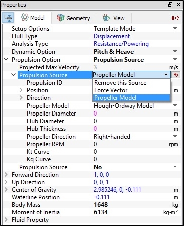
Figure 8.15 - Options under propulsion source in marine model |
 in
in Propeller Models
Uniform Thrust model
This model uses an approach to assume a uniform distribution of thrust over the propeller disc neglecting the torque. Hence it applies uniform axial momentum ( , which adds as momentum source terms
  in the momentum equation) across the propeller diameter. The axial momentum source term is expressed as:

|
8.6 |
where  is the thickness of the hub,

|
Radii of the hub. |

|
Radii of the propeller. |

|
Thrust whose magnitude must be provided. It is generally from propeller the  curve. curve. |
The tangential momentum source term is zero as we neglect the torque. The uniform thrust model study could be performed for either the full propeller or half depending on the geometry and the location of the propeller. This is controlled by the Whole Propeller option.
Hough - Ordway model
Hough-Ordway model uses the same disc approach to model the propeller. But it prescribes both the thrust and torque radial distribution ( and
and  , which adds as momentum source terms
  in the momentum equation) . The non-dimensional axial and tangential thrust distributions are given by:

|
8.7 |

|
8.8 |
where

|
8.9 |

|
8.10 |

|
8.11 |
where the non dimensional radius is defined as,

|
8.12 |
Here,

|
Radii of the hub. |

|
Radii of the propeller. |

|
Velocity. |

|
Obtained for the corresponding advance coefficient |
 from the
The data needed for these models are input using the Propeller Diameter, Hub Diameter, Hub Thickness, Propeller Direction, Propeller RPM, Kt Curve and Kq Curve options.