8.2.1 Geometry and Domain
The simulation of the propeller requires the understanding of the geometry of the propeller and the type of flow. Typically, propeller involves external flow around the rotating body. Hence no need to extract fluid volume. The general fluid volume of the propeller involves propeller geometry and bounding box around it. The prerequisite steps, before taking into Simerics-MP+ is described as follows:
Prerequisite steps
- The propeller geometry should not have gap, else mesh will leak into the propeller volume.
-
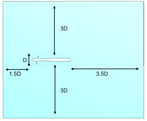
Ensure sufficient bounding box margin in the upstream, downstream and sides of the propeller. The bounding box can be created inside Simerics-MP+ using general mesher during meshing. For more details, refer Bounding Box Margins. In case of open water test, use the following dimensions as shown in Figure 8.77
- In case of tunnel test, use the exact dimensions.
Fluid Domain
This section explains a general fluid domain for the propeller simulation in Simerics-MP+.This fluid volume in a propeller is defined by bounding surfaces which encloses propeller. The propeller model primarily consists of the following parts/ volumes as shown in Figure 8.78
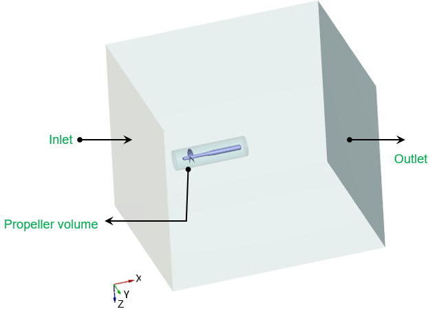
Inlet: The fluid enters through the inlet boundary. The inlet boundary specified as a pressure or flux.
Propeller Volume: Rotating region of propeller volume
Outlet: The fluid exits through the outlet boundary. The outlet boundary specified as a pressure or flux.
Bounding box: This includes, inlet, outlet, top and bottom surfaces. The top and bottom boundary are specified as pressure or wall.
For an example of the propeller simulation, refer Propeller Tutorial.