中文 English
You are here: Marine Templates and Tutorials > Propeller Template > Propeller Tutorial > Defining Physics and Conditions

Defining Physics and Conditions

The physics and conditions are specified as follows.

Adding Modules
  1. Click Select Modules in the Model Panel. The Physical Model Selection dialog box opens.
  2. Select Propeller, Turbulence and Cavitation under Available Modules and click Add.
  3. Click Close to close the Physical Model Selection dialog box.


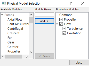
Figure 8.96 - Adding modules


Generating Operating Parameters
  1. Select Propeller in the Model Panel.
  2. Select Extended Mode for Setup Options in the Properties Panel.
  3. Select Simulation Method to Steady (Multiple Reference Frame).
  4. Enter Number of Blades as 3 under Pump Configuration list.
  5. Specify Rotor Center as 0,0,0.
  6. Enter the parameters for Angular Velocity Definition as follows:
  • Rotational DirectionClockwise

  • Rotational Speed: 600 rpm

  • Rotational Axis Vector: 1,0,0


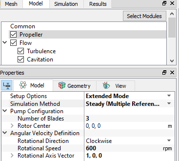
Figure 8.97 - Propeller operating parameters

Boundary Conditions

The boundary conditions are specified as follows:

Inlet
  1. Select outside_dir1_min from the Boundaries list under Volumes in the Geometric Entities Panel.
  2. Select Inlet from the Propeller drop-down list in the Model Tab of Properties Panel.
  3. Select Specified Pressure Inlet from the Flow drop-down list.
  4. Click Edit Expression icon in Pressure to open the Expression Editor dialog box .
  5. The sample expression text is under Calculations for advance ratio, torque and thrust coefficient, the user needs to copy and paste the expressions written under Description drop-down list for Global Expressions editor of Simerics-MP+ as shown in Figure 8.98.
  6. Click OK and enter p_init for the Pressure.
  7. Specify Velocity(optional) under Velocity Profile as ux,0,0.


  Note: The expressions specified also involve the calculations for the advance ratio (J), torque coefficient (KQ) and thrust coefficient (KT) of the propeller. For more information, refer to Propeller manual.


Figure 8.98 - Inlet conditions

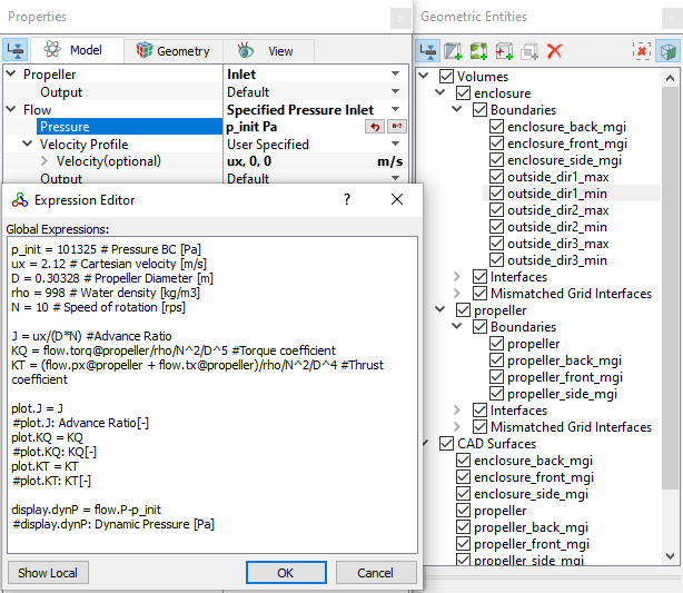
The following expressions are added in the Expression Editor to calculate the above quantities:


Rotor
  1. Select propeller from the Boundaries list in the Geometric Entities Panel.
  2. Select Rotor from the Propeller drop-down list in the Model Tab of Properties Panel.


  Note: The rotational parameters specified for Rotor boundary are same as the values defined under Propeller in the Model Panel. These values cannot be changed as indicated by blue font.


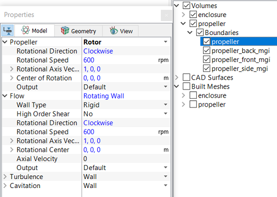
Figure 8.99 - Rotor conditions


Outlet
  1. Select outside_dir1_max, outside_dir2_max, outside_dir2_min, outside_dir3_max and outside_dir3_min from the Boundaries list in the Geometric Entities Panel.
  2. Select Outlet from the Propeller drop-down list in the Model Tab of the Properties Panel.
  3. Select Specified Pressure Outlet from the Flow drop-down list.
  4. Specify p_init for Pressure.
  5. Specify Back Flow Velocity(optional) under Velocity Profile as ux,0,0.


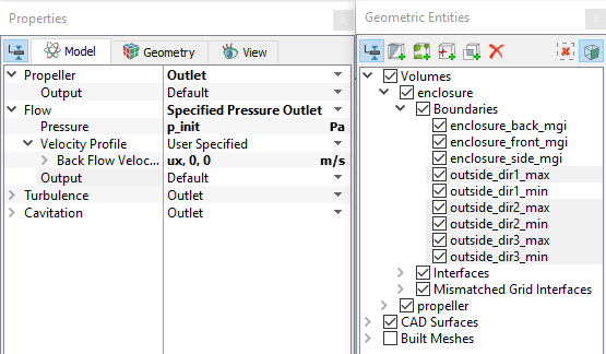
Figure 8.100 - Outlet conditions


Fluid Properties
  1. Select Volumes in the Geometric Entities Panel.
  2. Select Model Tab in the Properties Panel.
  3. Enter the parameters for Property list under Propeller as follows:
  • MaterialWater

  • Dynamic Viscosity: 0.001003 Pa-s

  • Density: 998 kg/m3

  • Liquid Bulk Modulus(B0): 2.15e+09 Pa
  • Liquid Reference Pressure: 101325 Pa
  • Saturation Pressure: 3610 Pa
  • Enter the parameters for Operating Conditions as follows:
    • Gas Mass Fraction2.3e-05

    • Operatting Temperature: 300 K


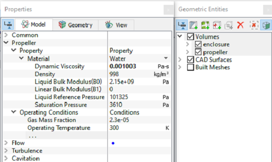
    Figure 8.101 - Fluid Properties


    Copyright © 2023 Simerics Inc.,