Conditions
This section explains the conditions related to the boundaries and the volumes in a propeller simulation.
The conditions for a desired boundary are accessed as follows:
Geometric Entities Panel > Boundaries > [Desired boundary]
Properties Panel > Model Tab >Propeller > [Desired options]

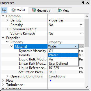
Figure 8.84 - Propeller-Conditions
- Rotor: This is used to assign boundary conditions for the rotor surfaces. The rotational properties of the rotor are set under the Angular Velocity Definition parameters.
- Inlet: This specifies an inlet boundary. The default inlet boundary for Propeller module uses a Specified Total Pressure as the flow boundary conditions. Additional boundary conditions for an Inlet boundary can be accessed using the Extended Mode.
- Outlet: This specifies an outlet boundary. The default outlet boundary for Propeller module uses a Specified Volumetric Flux as the Flow boundary conditions. Additional boundary conditions for an outlet boundary can be accessed using the Extended Mode.
- Rotating Wall: This boundary conditions of the Propeller module enables setting a rotational velocity on a boundary. This allows specifying an rpm and an axis of rotation for a selected boundary other than for a boundary of the rotor chamber. This boundary adds rotational sources to the momentum of the fluid (via the Flow module); but does not rotate the boundary. By default, this boundary conditions assumes the same values of rpm and axis of rotation as the rotors, but these parameters can be changed.
- Wall: This boundary condition corresponds to a solid boundary and assigns wall properties for Flow and other modules. Additional boundary conditions for this boundary (e.g. moving wall) can be accessed via the Flow module Wall boundary condition using the Extended Mode.
|
The Propeller template has following parameters assigned to the fluid volumes. The conditions for a desired volume are accessed as follows: Geometric Entities Panel > Volumes > [Desired Volume] Properties Panel > Model Tab > Propeller > [Desired options] The template has additional conditions which apply to selected volumes in the simulation under Propeller module. These below attributes apply to volumes only. Each volume may be assigned specific independent attributes.
|
Output
Primary and Derived variables can be integrated over a selected boundary and stored in the ASCII format file filename_integrals.txt for subsequent Post-Processing. The quantities available for output for the boundary depend on the boundary type.
The desired output can be activated for a selected boundary in the Model Tab of the Properties Panel. The outputs which can be activated are specified as User Select(Area, Normal).
For the boundaries specified as inlet and outlet, the output quantities available in the Plot Panel are Revolution Average Mass Flux, Revolution Average Volume Flux and can be displayed using X-Y Plots for respective boundary.
For the boundaries specified as rotor, the output quantity available in the Plot Panel is Revolution Averaged Power and can be displayed using X-Y Plots for respective Boundary.
The Output Properties other than User Select, are automatically calculated and stored in the output file as Filename_integrals.txt and may be selected and displayed in X-Y Plots .
When monitoring Points are created as part of the simulation, the output quantities are stored in the ASCII format file filename_points.txt for subsequent Post-Processing.
Propeller Post-processing
Calculations for advance ratio, torque and thrust coefficient
Generally, propeller performance is evaluated using the advance ratio (J), torque coefficient (KQ) and thrust coefficient (KT). The Expression Editor in Simerics-MP+ is used to evaluate the above quantities.
The expressions for the calculations are as follows:
Advance Ratio,
|
|

where  is the velocity in m/s,
  is the diameter of the propeller in m and
  is the speed of rotation in rps.
Torque Coefficient,
|
|

where  is the torque in Nm,
  is the density in kg/m3,
  is the diameter of the propeller in m and
  is the speed of rotation in rps.
Thrust Coefficient,
|
|

where,  is the thrust in N (sum of the pressure and shear forces on the propeller blade),
  is the density in kg/m3,
  is the diameter of the propeller in m and
  is the speed of rotation in rps.
For more information, refer Propeller Tutorial.
|
Note: Typically in Marine application, |
 indicates thrust i.e. sum of the pressure and shear forces and in other applications,
  indicates Torque.